00191374-04.pdf - 第173页
Adjustment In structions SIPLACE HS-50 9 Calibrat ion of SIPLACE HS-50 (in cl. SITEST v ersion 501.xx) Softwareversion SR.501.xx Edition 12/00 9.6 Calibration Collect & Place Head Nozzle Changer 173 &DO…
172
9 Calibration of SIPLACE HS-50 (incl. SITEST version 501.xx) Adjustment Instructions SIPLACE HS-50
9.5 Calibration of Calibration Position Softwareversion SR.501.xx Edition 12/00
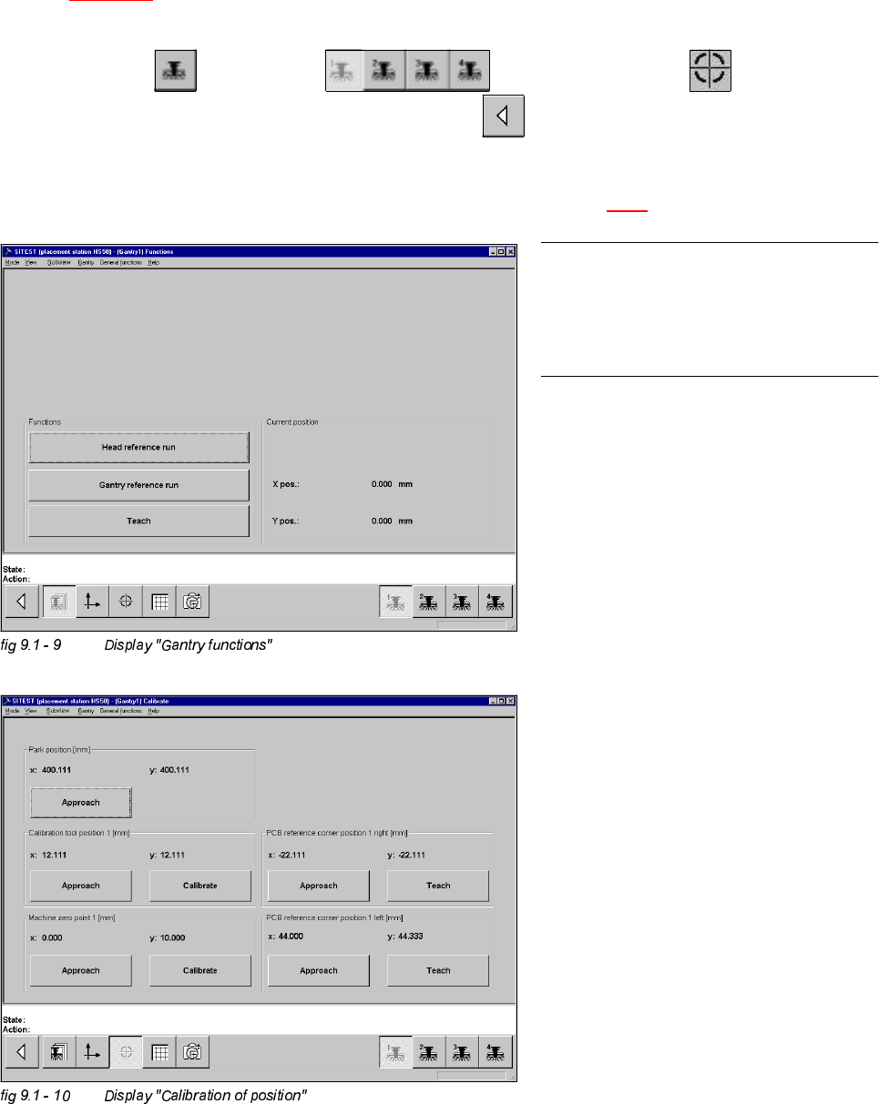
&DOLEUDWLRQRI&DOLEUDWLRQ3RVLWLRQ
Example: Placement area 1.
Å Insert the calibration tool in to the "calibration bag 1" in placement area 1.
(See
fig 9.1 - 1).
6,7(67
Å Select "Gantry" ==> "Gantry 1" ==> "Calibrate position" ==>
"Calibrate (field "calibration position 1")"==> "Main view" ==> "Save machine data".
Å Proceed under section "Calibration of the Pick-Up Height". (See section 9.6.3).
NOTE
Proceed the same way with gantry 2, in
order to determine the calibration position
in placement area 2.
Adjustment Instructions SIPLACE HS-50 9 Calibration of SIPLACE HS-50 (incl. SITEST version 501.xx)
Softwareversion SR.501.xx Edition 12/00 9.6 Calibration Collect & Place Head Nozzle Changer
173
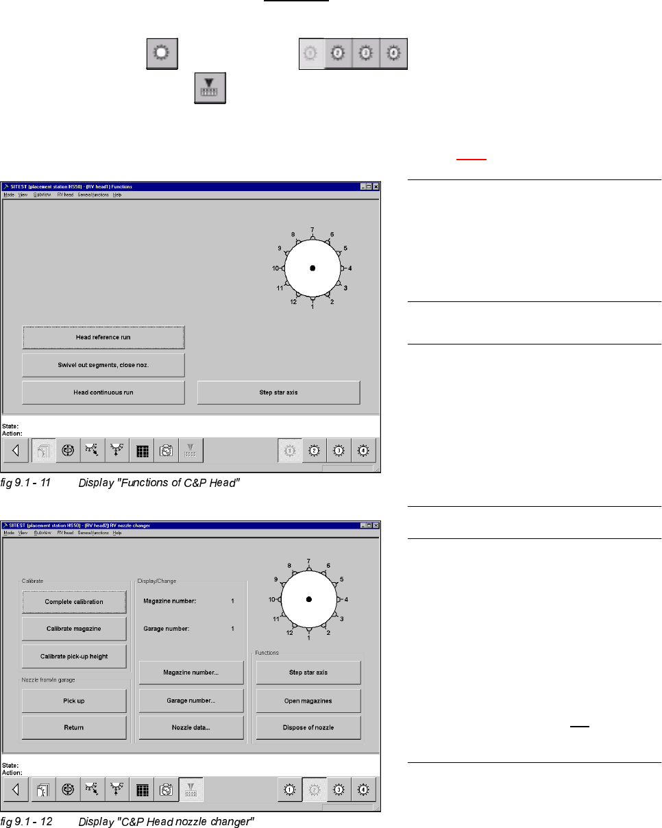
&DOLEUDWLRQ&ROOHFW3ODFH+HDG1R]]OH&KDQJHU
&RPSOHWH&DOLEUDWLRQ
Example: Nozzle changer for C&P Head 1, completely supplied with all 5 or 10 magazines.
6,7(67
Å Select "C&P Heads" ==> "C&P Head 1" ==>
"C&P Head nozzle changer" ==> "Complete calibration".
Å Proceed under section "Calibration of the Pick-Up Height". (See section 9.6.3).
NOTE
Make sure that the calibration data for the
PCB camera, the segment offset II (C&P
PCB camera offset) and the machine zero
point have been determined already.
NOTE
A nozzle changer contains 5 magazines
maximum, with 12 nozzle garages each.
For every single C&P Head, 2 nozzle
changers may be installed. During
calibration these will be handled like one
single nozzle changer with 10 magazines.
NOTE
The function "Complete calibration" is
used, if the nozzle changer is completely
loaded with all 5 or 10 magazines.
All 12 nozzles must be on the C&P Head.
With the help of the function "Calibrate
current magazine", x- and y-values must
be individually determined for each
magazine if the changer is not
completely
loaded.
174
9 Calibration of SIPLACE HS-50 (incl. SITEST version 501.xx) Adjustment Instructions SIPLACE HS-50
9.6 Calibration Collect & Place Head Nozzle Changer Softwareversion SR.501.xx Edition 12/00
NOTE
The pick-up height must be determined for
each magazine.
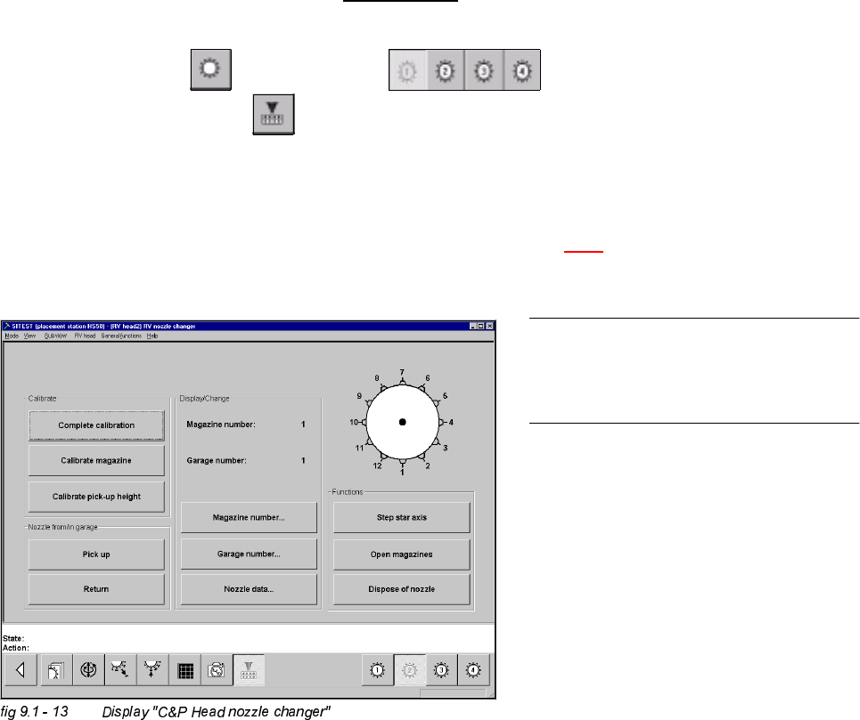
&DOLEUDWLRQRIWKH&XUUHQW0DJD]LQH
Example: Nozzle changer for C&P Head 1, not completely loaded with all magazines.
6,7(67
Å Select "C&P Heads" ==> "C&P Head 1" ==>
"C&P Head nozzle changer" ==> "Magazine number..." ==> "Type in magazine number and
accept" ==> "Calibrate current magazine".Repeat these instructions with all magazines.
Å Proceed under section "Calibration of Pick-Up Height". (See section 9.6.3).