00191374-04.pdf - 第27页
Adjus t ment In str uc tio ns SI PLA CE HS- 50 2 Operational Safety Edition 12/00 2.2 Safety Equipm ent 27 )XQFWLRQ If one of the protec tive co vers is folde d up or one of the c overs on th e PCB c onveyor is rais ed, …
2 Operational Safety Adjustment Instructions SIPLACE HS-50
2.2 Safety Equipment Edition 12/00
26
6DIHW\(TXLSPHQW
3URWHFWLYH&RYHUV
.(<
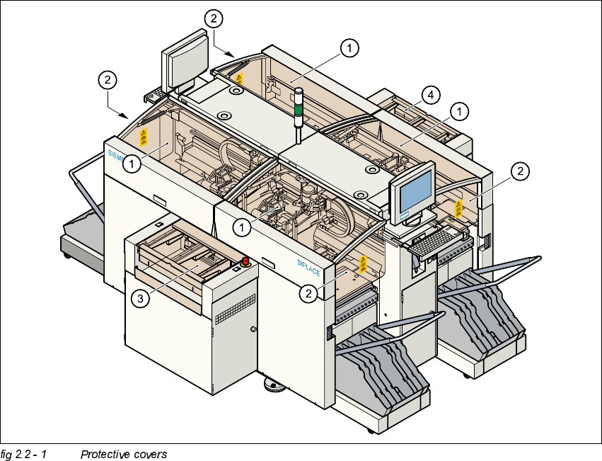
The travelling range of the gantries is covered by four protective covers which can be folded up.
Side panels prevent access to the inside of the placement system from the side. The covers over
the input and output belts of the PCB conveyor and the guards on the input and output belts
prevent access to the PCB conveyor.
(1) Protective covers
(2) Safety panels
(3) Cover and guard on the input conveyor
(4) Cover and guard on the output conveyor
Adjustment Instructions SIPLACE HS-50 2 Operational Safety
Edition 12/00 2.2 Safety Equipment
27
)XQFWLRQ
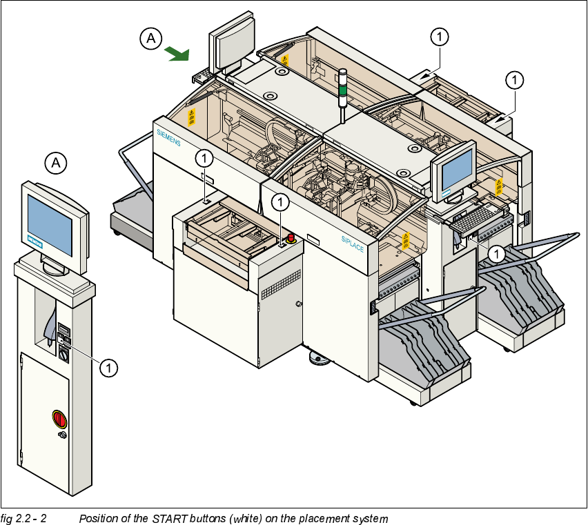
If one of the protective covers is folded up or one of the covers on the PCB conveyor is raised, the
power supply to the gantry axes will be interrupted at once. The gantry axes will stop.
– The message "Close covers" will appear on screen.
Å Close the protective covers and press one of the START buttons to continue placement.
.(<
(1) START button (white) on the system
2 Operational Safety Adjustment Instructions SIPLACE HS-50
2.2 Safety Equipment Edition 12/00
28
*XDUGRQWKH,QSXW2XWSXW&RQYH\RU
DANGER
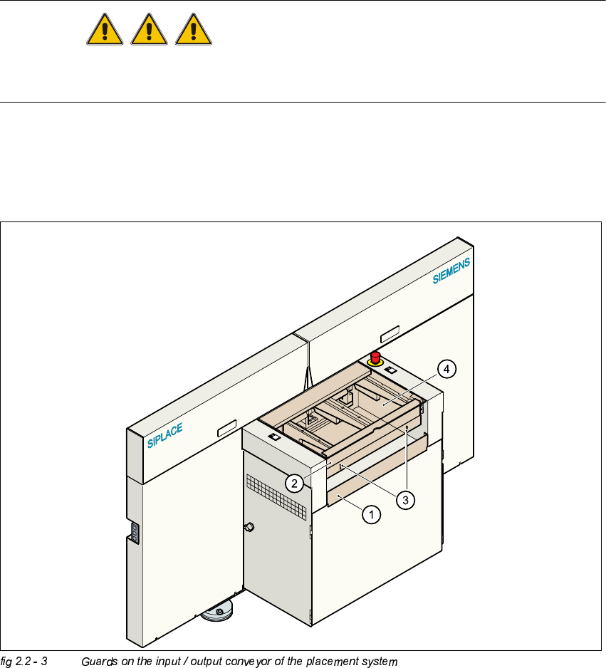
The guard must always be set to the height of the PCB to be processed. Ensure that the gap
between the guard and the safety bar is as small as possible.
– Guards are fitted on the input and output belts of the PCB conveyor.
Å The height of the guard must be set using the slots so that the processed PCB can travel
through.
.(<
(1) Safety bar (fixed)
(2) Guards (adjustable)
(3) Slots for adjusting the height
(4) Cover