00191374-04.pdf - 第152页
7 Collect & Place Head DLM1 Adjustment Instructions SIPLACE HS-50 7.4 Dynamic Adjustment of the Axes Edition 12/00 152 0 HDVXUHPH QW6HWXSIRU$[LV$GMXVWPH QW V ready for operat ion enable outpu t stage effect…
Adjustment Instructions SIPLACE HS-50 7 Collect & Place Head DLM1
Edition 12/00 7.4 Dynamic Adjustment of the Axes
151
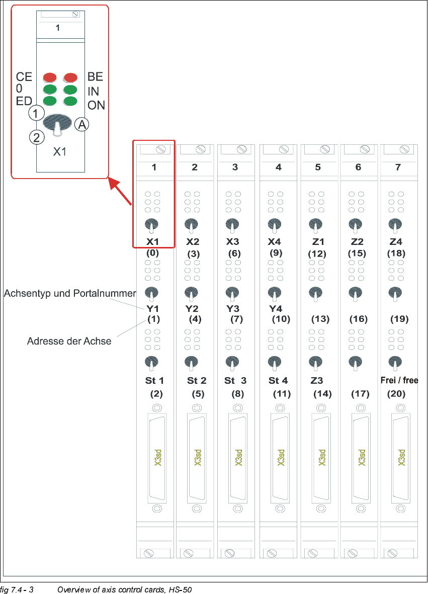
2YHUYLHZRI$[HV&RQWURO&DUGV+6
type of axis and gantry number
adress of axis
'3 '3
'3
'3
CE = Counting error
0 = Zero pulse
ED = End signal
BE = General error, module error
IN = Initialized
ON = Servo ON
(A) Axis enable switch
(1) Servo ON
(2) Servo OFF
7 Collect & Place Head DLM1 Adjustment Instructions SIPLACE HS-50
7.4 Dynamic Adjustment of the Axes Edition 12/00
152
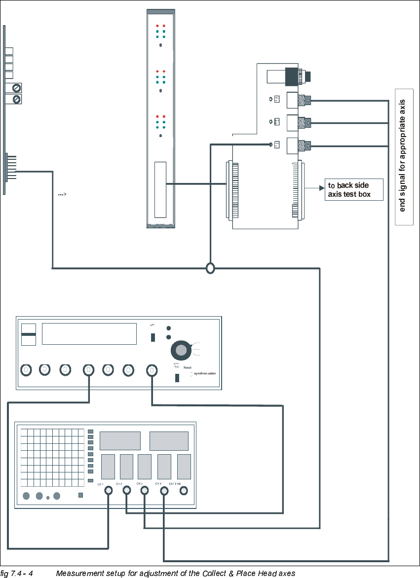
0HDVXUHPHQW6HWXSIRU$[LV$GMXVWPHQWV
ready for operation
enable output stage
effective current limit
error
tacho
P-gain
axis 0
axis 1
axis 2
measuring current of star - axis
changeover switch pressed down
end signal axis 0
end signal axis 1
end signal axis 2
interface
test adapter
axis test box
actual current
with RC - filter
current measuring of dp - axis and z-axis only
interface axis control card
interface axis test box
track A track B zero pulse Vnom force end signal deviat. of pos.
dgt
zero pulse
end signal
axis 0
axis 1
axis 2
OFF
ON
Vnominal
d
e
v
i
a
t
i
o
n
o
f
p
o
s
i
t
i
o
n
c
u
r
r
e
n
t
v
a
l
u
e
e
n
d
s
i
g
n
a
l
Adjustment Instructions SIPLACE HS-50 7 Collect & Place Head DLM1
Edition 12/00 7.4 Dynamic Adjustment of the Axes
153
6WDU$[LV
*HQHUDO3UHSDUDWLRQ
Å Start SITEST.
Å Turn on the compressed air.
Å Prepare the measurement setup for the star - axis according to fig 7.4 - 4.
Å Set the oscilloscope according to the table below.
Å Perform a head reference run.
NOTE
Use an RC - filter to record the current curve
Measure the end signal on the adapter board "axis control card", (the lowest BNC socket), with
the switch activated.
Measure the nominal current of the star - axis on the "measuring adapter axis control card current
measure star" (Do not connect GND).
&KHFN3*DLQ
NOTE
An adjustment of the star - axis on the servo amplifier is not possible.
Adjustment parameters are preset by board VC10 Controller. This board is on the axis control card
1, or 2, 3 or 4.
6,7(67
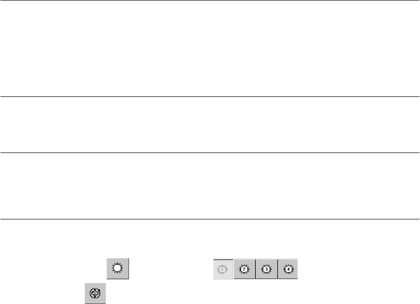
Å Select "C&P Heads" ==> "Select head" ==>
"Axis functions" ==> "Select star - axis" ==> "Continuous run, star" ==> "Input: Waiting
time 500 ms" ==> "Accept".
Å If necessary, press the START button.