00191374-04.pdf - 第130页
6 Gantries Adjust men t Ins tru ct ion s SIPL ACE H S-50 6.6 Calibration of the A nti - Crash Board Edition 12/00 130 NOTE Adjustme nts are iden tical for b oth gan try groups. CAUTION Perform these adj ustments onl y …
Adjustment Instructions SIPLACE HS-50 6 Gantries
Edition 12/00 6.6 Calibration of the Anti - Crash Board
129
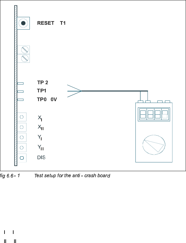
&DOLEUDWLRQRIWKH$QWL&UDVK%RDUG
7HVW(TXLSPHQW
– Digital multimeter
– SITEST software
– Anti - crash board for HS-50
7HVW6HWXS
.(<
TP2 = Signal
R82, R92 = Potentiometer
TP1 = Signal
X
, Y = "Error" message for the axes of the left gantry in each work area.
X
, Y = "Error" message for the axes of the right gantry in each work area.
(Viewpoint from input conveyor).
DIS = Message: Distance sensor activated.
R 82
R 92

6 Gantries Adjustment Instructions SIPLACE HS-50
6.6 Calibration of the Anti - Crash Board Edition 12/00
130
NOTE
Adjustments are identical for both gantry groups.
CAUTION
Perform these adjustments only after you pressed the EMERGENCY STOP button!
$GMXVWPHQWRI'LVWDQFH6HQVRU6HQVLWLYLW\
Å
Connect the digital multimeter of the anti - crash board to pin TP 0 (0V) and pin TP 1 (signal).
Å Move both gantries together.
Å Use the adjusting screw to set the voltage at the distance sensor to 6V - +/- 0,1 V.
Å Move the two gantries together until a distance of 100 mm is reached.
(Elastomer spring up to opposite plane).
– The voltage must reach a value of approx. 2V.
&DOLEUDWLRQRIWKH$QWL&UDVK%RDUG
Å
Connect the digital multimeter to the anti - crash board at pin TP2 (signal) and pin TP0 (0V).
Å Move both gantries together.
Å Use the potentiometer R82 to adjust the voltage to 0V- +/- 0.05 V.
Å Move the two gantries together until a distance of 100 mm is reached.
Å Use the potentiometer R92 to adjust the voltage to 10V- +/- 0.05 V.
Å Check the 0V- setting one more time.
Å Repeat the calibration if the reached value is incorrect.
)XQFWLRQ&RQWURORIWKH'LVWDQFH6HQVRU
3UHSDUDWLRQ
Å Perform a reference run.
7HVWLQJ3ODFHPHQW$UHDV,DQG,,
Å In placement area I, attach a piece of paper in the middle of the machine, at the height of the
distance sensor.
Adjustment Instructions SIPLACE HS-50 6 Gantries
Edition 12/00 6.6 Calibration of the Anti - Crash Board
131
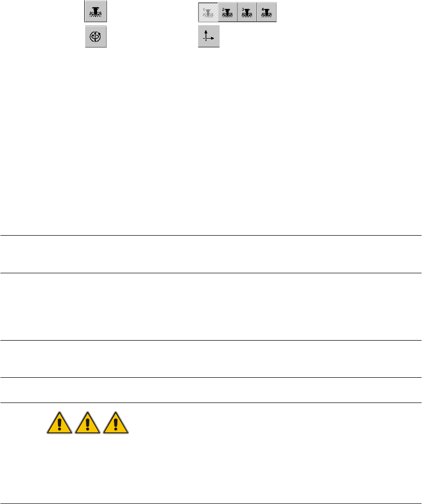
6,7(67
Å Select "Gantry" ==> "Select gantry" ==>
"Axis functions" ==> "Select y-axis" ==> "Position the axis" ==> "Edit values and
accept for target position = 1 300,000 dgts".
Å Press the START button.
– The axis will stop at the obstacle. The distance sensor has triggered.
Å Press the EMERGENCY STOP button and remove the obstacle.
Å Press RESET on the anti - crash board.
Å Release the EMERGENCY STOP button and press the START button.
Å Perform a gantry reference run.
Å Perform the same test with placement area II.
NOTE
For placement area I, select "gantry 3". Edit and accept a target position of 600,000 dgts.
)XQFWLRQV&RQWURORIWKH$QWL&UDVK%RDUG
NOTE
This test is identical for all gantry groups.
DANGER
You must press the EMERGENCY STOP button BEFORE you activate RESET on the anti - crash
board.
If you do not press the EMERGENCY STOP button, the axis will continue traversing immediately
after RESET.