00191374-04.pdf - 第121页
Adjus t ment In str uc tio ns SI PLA CE HS- 50 6 Gantries Edition 12/00 6.5 Dynamic A djustment of the X - and Y- A xes 121 2YHUYLH ZRI$[HV&RQWURO&DUGV+6 type of ax is and g antry nu mber adres s …

6 Gantries Adjustment Instructions SIPLACE HS-50
6.5 Dynamic Adjustment of the X- and Y- Axes Edition 12/00
120
.(<
TBS 200 / 10X = Servo board x-axis
TBS 200 / 15Y = Servo board y-axis
(1) LED: Ready for operation
(2) LED: Servo enable
(3) LED: I
RMS
limit
(4) LED: Error
MP1 = Nominal current "I-S (U)"
MP2 = Nominal current "I-S (W)"
MP3 = Actual current "I-ist (U)"
MP4 = Actual current "I-ist (W)"
MP5 = "U-nominal (U)"
MP6 = "U-nominal (W)"
MP7 = Free
MP8 = Reference potential "0V"
NOTE
For a proper triggering connect the endsignal and the nominal current.
Adjustment Instructions SIPLACE HS-50 6 Gantries
Edition 12/00 6.5 Dynamic Adjustment of the X- and Y- Axes
121
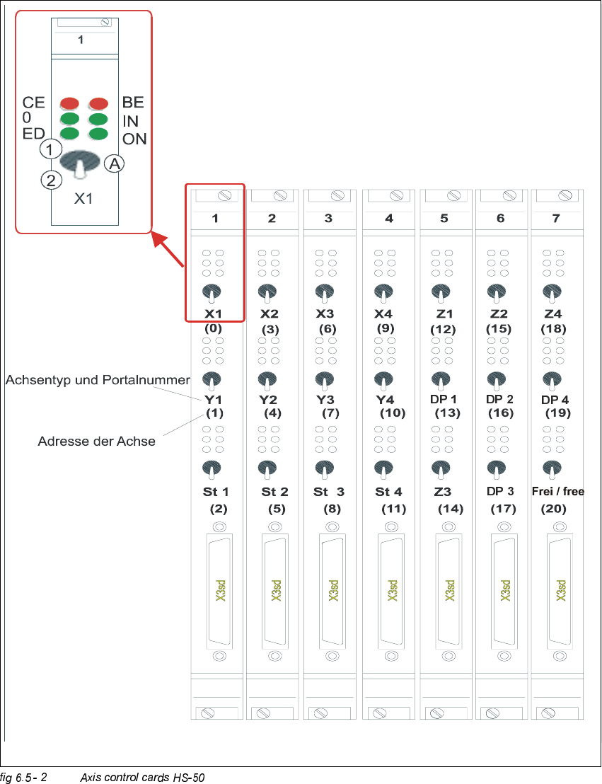
2YHUYLHZRI$[HV&RQWURO&DUGV+6
type of axis and gantry number
adress of axis
CE = Counting error
0 = Zero pulse
ED = End signal
BE = General error, module error
IN = Initialized
ON = Servo ON
(A) "Axis enable" switch
(1) Servo ON
6 Gantries Adjustment Instructions SIPLACE HS-50
6.5 Dynamic Adjustment of the X- and Y- Axes Edition 12/00
122
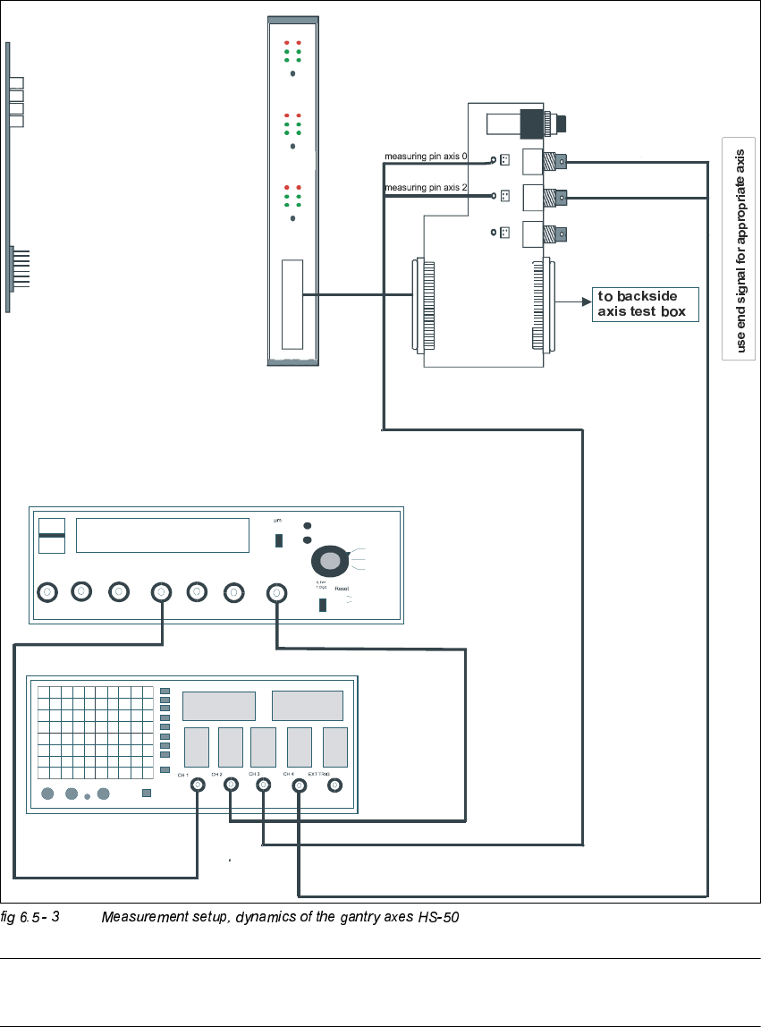
0HDVXUHPHQW6HWXSIRU$[LV$GMXVWPHQWV
NOTE
The current value measured at the adapter board is actual, not (commuted) nominal.
axis 2
Vnominal
ready for operation
enable output stage
effective current limit
error
interface
test adapter
axis test box
i
n
t
e
r
f
a
c
e
a
x
i
s
c
o
n
t
r
o
l
c
a
r
d
i
n
t
e
r
f
a
c
e
a
x
i
s
t
e
s
t
b
o
x
changeover switch pressed down
end signal axis 2
end signal axis 0
d
e
v
i
a
t
i
o
n
o
f
p
o
s
i
t
i
o
n
n
o
m
i
n
a
l
c
u
r
r
e
n
t
e
n
d
s
i
g
n
a
l
track A track B zero pulse Vnom force end signal deviat. of pos.
dgt
zero pulse
end signa
l
axis 0
axis 1
axis 2
OFF
ON
synchronization
axis 0
axis 1
axis 2