00191374-04.pdf - 第89页
Adjustment Inst ructions SIPLACE HS-50 5 Single an d Dual PCB Conveyor Edition 12/00 5.1 Settings and I llustrations 89 &RQYH\RU&RQWUROZLW KLQWHJUDWH G6/,2763
5 Single and Dual PCB Conveyor Adjustment Instructions SIPLACE HS-50
5.1 Settings and Illustrations Edition 12/00
88
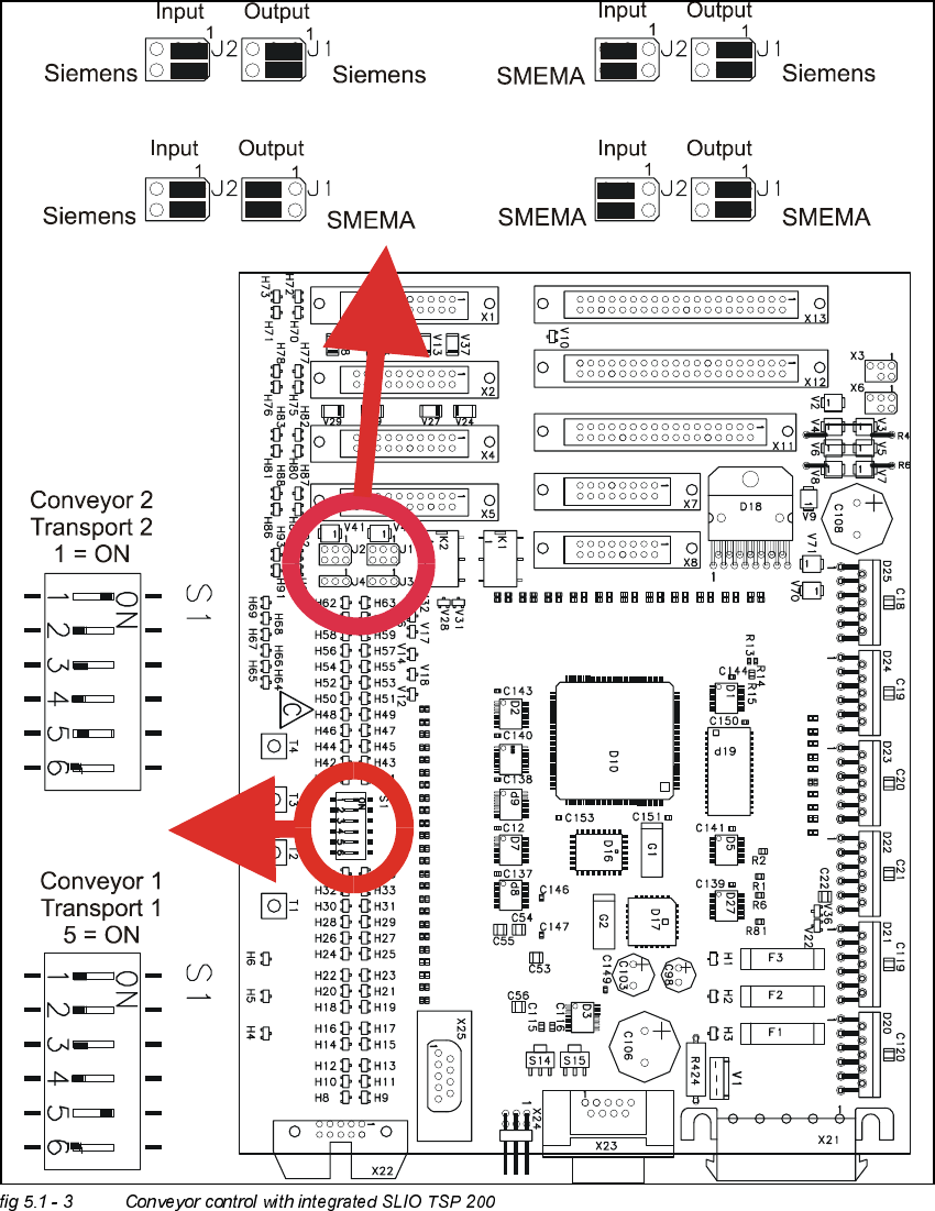
.(<
(1) SLIO module 1 = A2
(2) SLIO module 2 = A3
(3) SLIO module 3 = option
(4) SLIO module 4 = option
(5) SLIO module 5 = PCB conveyor 1
(6) SLIO module 6 = PCB conveyor 2 (only with dual conveyor)
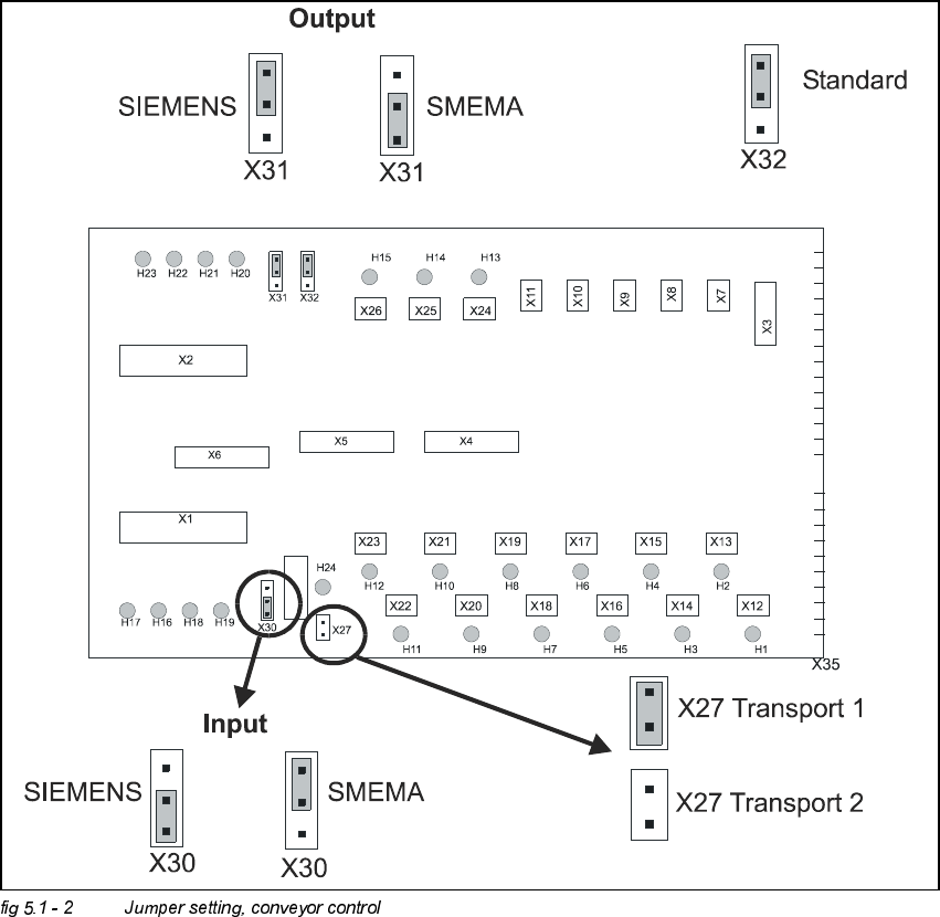
&RQYH\RU&RQWURO
Transportsteuerung / conveyor control
Mat.Nr. / mat. no: 00329219 - 02
/
transport 1
/
transport 2
Adjustment Instructions SIPLACE HS-50 5 Single and Dual PCB Conveyor
Edition 12/00 5.1 Settings and Illustrations
89
&RQYH\RU&RQWUROZLWKLQWHJUDWHG6/,2763

5 Single and Dual PCB Conveyor Adjustment Instructions SIPLACE HS-50
5.2 Adjustment of Supersonic Sensitivity Edition 12/00
90
$GMXVWPHQWRI6XSHUVRQLF6HQVLWLYLW\
Å Set conveyor width to minimum width.
NOTE
Adjusting the proximity switches "input /output conveyor belt", make sure that the proximity
switches do not switch to the movable bearers of the conveyor belt.
– The amplifiers for the adjustment of the ultrasonic sensors are located behind the door of the
right side of the input conveyor belt and behind the door above the servo unit of the output
conveyor belt.
,QSXW&RQYH\RU
Å Slide the PCB over the proximity switch "Input conveyor".
Å Turn the adjusting screw on the amplifier of the proximity switch "Input conveyor" fully counter-
clockwise.
– The yellow LED of the amplifier begins to flash.
Å Slowly, turn the adjusting screw of the proximity switch amplifier to the right, until the LED light
remains illuminated.
Å Hold the PCB approximately 5 mm above the PCB conveyor.
– The LED must go out.
Å Adjust again, if the switching point of the proximity switch remains outside the
selected range.
&HQWHU&RQYH\RU
Å Slide the PCB over the proximity switch "Center conveyor".
Å Push the clamping of the center conveyor upward, if the clamping system is shut.
Å Move the PCB to the proximity switch "Center conveyor".
Å Turn the adjusting screw of the proximity switch amplifier "Center conveyor" fully counterclock-
wise.
– The yellow LED of the amplifier begins to flash.
Å Slowly, turn the adjusting screw of the proximity switch amplifier to the right, until the LED light
remains illuminated.
Å Hold the PCB approximately 5 mm above the PCB conveyor.