00191374-04.pdf - 第142页
7 Collect & Place Head DLM1 Adjustment Instructions SIPLACE HS-50 7.3 Adjustments E dition 12/00 142 .H\ WR)LJ (1) M2 x 4 h exago n socket-h ead screw (2) S top p iece (3) 2 x M2.5 x 8 he xagon socket- he…
Adjustment Instructions SIPLACE HS-50 7 Collect & Place Head DLM1
Edition 12/00 7.3 Adjustments
141
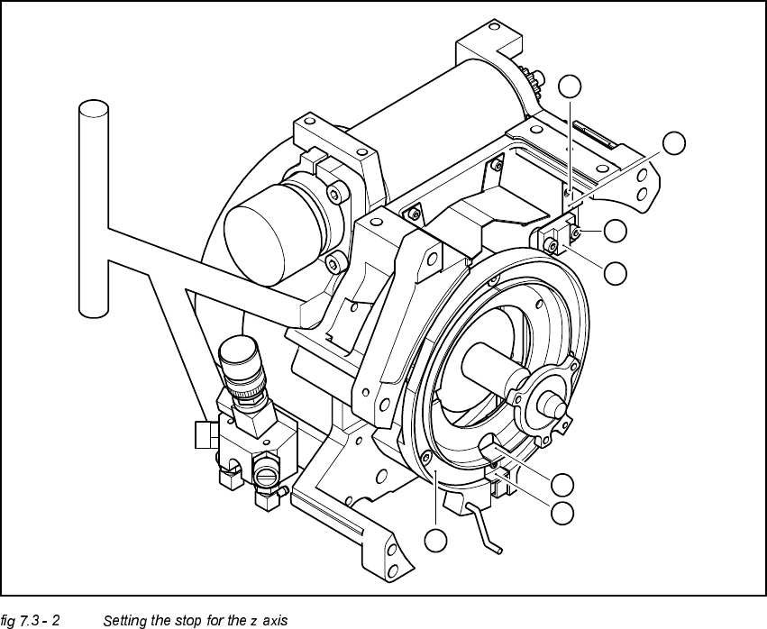
6HWWLQJWKHVWRSIRUWKH=D[LV
7RROVDQGHTXLSPHQW
– Set of DIN 911 Allen keys
– Gauge for z axis, from item no. 00331308-01
6HWWLQJV
Å Dismantle the front part of the revolver head as described in section 10.7.2, page 10 - 29 in the
Service manual.
Å Dismantle the star as described in the Service manual.
NOTE
The Z-axis must be correctly mounted (see section. 8.3.1)
Å Screw the stop piece with both hexagon socket screws M2.5x8 (position 3 in figure 8.3.2)
tightly to the drive belt, so that the clamping device is firmly fixed between the teeth of the drive
belt. (see fig.)
Å Carefully raise the Z-axis by hand, until the snap jaws (Pos. 5) are at least above the raceway
(Pos. 6).
Å Put the raceway with the Z-axis gauge into the position marked A.
Å Unscrew the hexagon socket screw of the stop piece. (Pos. 1 in fig. 8.3.2)
Å Insert the stop piece in to the stopping face until contact is made.(Pos. 2 in fig. 8.3.2)
Å Fix the stop piece to the hexagon socket screw M2x4.
Do not use a ball-end-allen wrench.
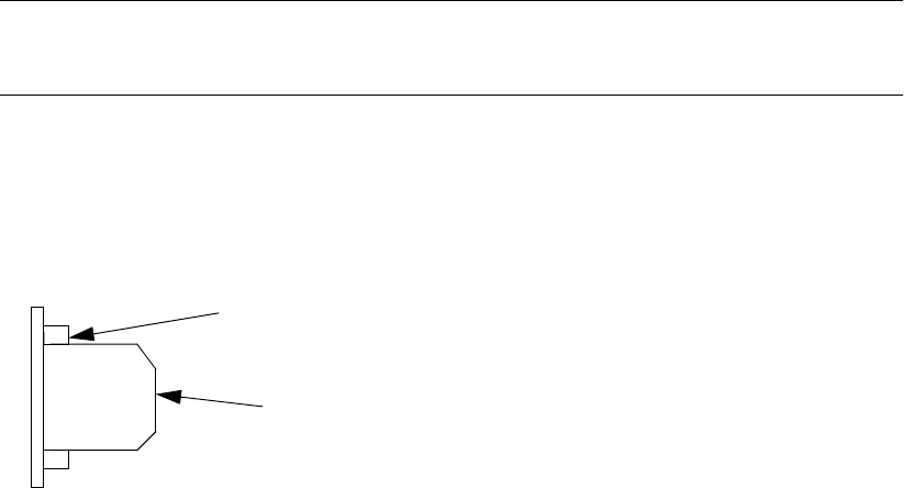
drivebelt tooth
Clamping device between the
teeth of the drive belt
7 Collect & Place Head DLM1 Adjustment Instructions SIPLACE HS-50
7.3 Adjustments Edition 12/00
142
.H\WR)LJ
(1) M2x4 hexagon socket-head screw
(2) Stop piece
(3) 2 x M2.5x8 hexagon socket-head screw
(4) Stop
(5) Snap jaws of the z axis
(6) Raceway
(A) Insert the z axis gauge here
6
A
5
4
3
2
1
Adjustment Instructions SIPLACE HS-50 7 Collect & Place Head DLM1
Edition 12/00 7.3 Adjustments
143
$LU3UHVVXUH9DOXHV
7RROVDQG'HYLFHV
– A set of slotted screw drivers
– Compressed air testing device
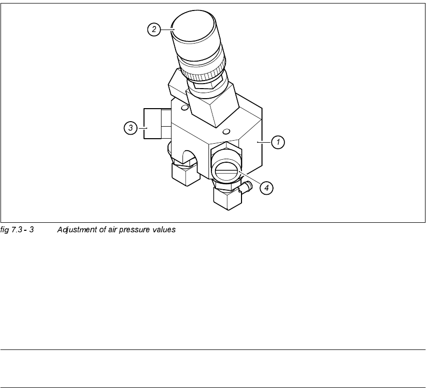
$GMXVWPHQWRI$LU3UHVVXUH9DOXHV
.(<
(1) Forced air unit / DLM1
(2) Micro - relay valve
(3) Restrictor valve for the reject circuit
(4) Restrictor valve for the pick - up / placement circuit
NOTE
Use a nozzle type 914 to adjust the blast air.