00191374-04.pdf - 第80页
4 Overview Voltages Adjust ment Inst ruc ti ons SI PLA CE HS- 50 4.6 Measuring Voltages of the Power Supply Unit Edition 12/00 80 0 HDVXULQJ9 ROW DJHV RQ5HFWLI LHUV9WR 9 The graphi c belo w display s the po…

Adjustment Instructions SIPLACE HS-50 4 Overview Voltages
Edition 12/00 4.6 Measuring Voltages of the Power Supply Unit
79
0RGXOH 'HVLJQDWLRQ &ODPSV 9ROWDJHV
X1
connecting terminal panel
power supply
U, V, W
3 x 204 VAC / 3 x 380 VAC /
3 x 400 VAC / 3 x 415 VAC
BU1
service socket 115 VAC / 220 VAC / 230VAC / 240 VAC
S1
main switch
1, 3, 5 u.
2, 4, 6
3 x 204 VAC / 3 x 380 VAC /
3 x 400 VAC / 3 x 415 VAC
MS1
motor protective switch
1, 3, 5 u.
2, 4, 6
3 x 204 VAC / 3 x 380 VAC /
3 x 400 VAC / 3 x 415 VAC
SZ1
main contactor
1, 3, 5 u.
2, 4, 6
3 x 204 VAC / 3 x 380 VAC
3 x 400 VAC / 3 x 415 VAC
MS3
MS4
MS5
MS6
motor protective switch
PCB conveyor 1
motor protective switch
PCB conveyor 2 (option)
1, 3, 5 u.
2, 4, 6
1, 3, 5 u.
2, 4, 6
3 x 230 VAC
3 x 230 VAC
3 x 230 VAC
3 x 230 VAC
SZ2
contactor
1, 3, 5
2, 4, 6
3 x 140 VAC
3 x 140 VAC
SZ3
contactor
1, 3, 5
2, 4, 6
3 x 140 VAC
3 x 140 VAC
SZ23
contactor
1, 3, 5
2, 4, 6
3 x 140 VAC
3 x 140 VAC
SZ4
contactor
A1 (+) - A2 (-)
1, 2
3, 4
5, 6
24 VDC
24 VDC against ground
24 VDC against ground
24 VDC against ground
SSK
protective contactor
combination
L+, X3, X5 24 VDC against ground
F1
fuse
service socket
1, 2
115 VAC / 220 VAC
230 VAC / 240 VAC
against N on the connecting terminal panel 1
F3
fuse
board net
1, 3, 5
2, 4, 6
3 x 230 VAC
F4
fuse
x- / y- axis
1, 3, 5
2, 4, 6
3 x 140 VAC
F5
fuse
star - axis
1, 2 100 VDC against minus of rectifier V3.
F6
fuse
z- and dp - axis
1, 2 30 VDC against minus of rectifier of V4.
4 Overview Voltages Adjustment Instructions SIPLACE HS-50
4.6 Measuring Voltages of the Power Supply Unit Edition 12/00
80
0HDVXULQJ9ROWDJHVRQ5HFWLILHUV9WR9
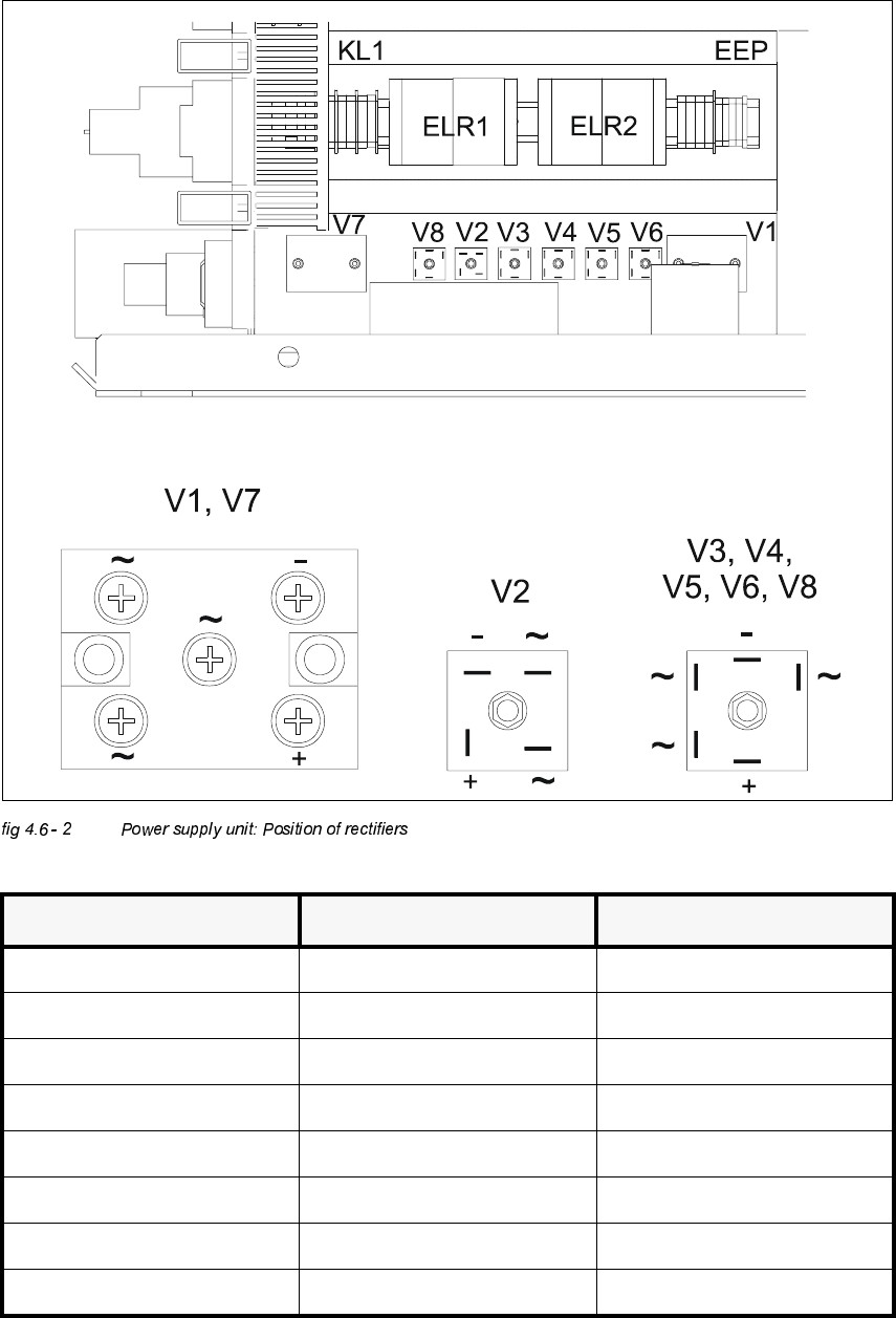
The graphic below displays the position of rectifiers V1 to V7 as well as their pin configurations.
Å In order to measure the voltages of rectifiers V1 and V7, you must first remove the the
protective plexiglass pane.
DANGER! RISK OF LIFE THROUGH ELECTROCUTION
Å Use the main switch to turn off the system.
Å Disengage the system from the power supply.
Å Wait approximately 1 min, until the residual voltages have decreased to a harmless value.
(Electrolytic capacitor C1).
Å Untighten both M5 - cap screws of rectifiers V1 and V7.
Å Remove the protective plexiglass pane.
Å Turn on the system and start it.
Å Measure the voltages.
NOTE
The system must have been started first, otherwise there will be no voltage on the rectifier V1
(3 x 140 VAC). V1 generates the supply voltage of 200 VDC from the 3 x 140 VAC for the servo
amplifier gantry axes and 100 VDC for the servo amplifier of the star - axes.
These 100 VDC and 6 VDC are fed to the alternating voltage inputs of rectifier V2 .
Rectifier V2 serves to keep the switch between 6 VDC and 100 VDC free of interrupts.
Before the start of the system, there are only 6 VDC on the rectifier V1.
F7
fuse
component table (feeder)
1, 2
38 VDC against minus of rectifier V5.
(See fig 4.6 - 2).
F8
fuse
PCB conveyor
1, 2
38 VDC against minus of rectifier V5.
(See fig 4.6 - 2)
F9
fuse
component table (logic)
1, 2
8 VDC against minus of rectifier V6.
(See fig 4.6 - 2)
F10
fuse
control unit
1, 2
52 VDC against minus of rectifier V7.
(See fig 4.6 - 2)
F11
fuse
in rush limiter
1, 2
30 VDC against minus of rectifier V8.
(See fig 4.6 - 2).
Adjustment Instructions SIPLACE HS-50 4 Overview Voltages
Edition 12/00 4.6 Measuring Voltages of the Power Supply Unit
81
5HFWLILHU ,QSXW 2XWSXW
V1 3 x 140 VAC 200 VDC
V2 100 VDC 100 VDC
V3 3 x 5 VAC 6 VDC
V4 3 x 24 VAC 30 VDC
V5 3 x 30 VAC 38 VDC
V6 3 x 6 VAC 8 VDC
V7 3 x 40 VAC 50 VDC
V8 3 x 24 VAC 30 VDC