00191374-04.pdf - 第51页
Adjus t ment In str uc tio ns SI PLA CE HS- 50 2 Operational Safety Edition 12/00 2.6 Locking Up of Machine and Tagging of Warn Signs 51 /RFNLQJ 8S RI 0 DFK LQH DQG 7 DJJLQJ RI : DUQ 6LJQV 3XUSRVHDQG…

2 Operational Safety Adjustment Instructions SIPLACE HS-50
2.5 Energy Level after Switching Off Main Switch Edition 12/00
50
3ODFHPHQW6\VWHP6ZLWFKHG2IIDWWKH0DLQ6ZLWFKDQG'LVFRQQHFWHG
The automatic placement system is cut off from all electricity , apart from slight residual voltages
in the servo unit.
&RPSUHVVHG$LU&RQGLWLRQVLQWKH0DFKLQHDIWHU6ZLWFKLQJ2IIWKH0DLQ
6ZLWFK
When the system is switched off at the main switch (item 1 in fig 2.4 - 1) or if the power supply
fails, the electrically controlled main valve Y1 of the compressed air unit closes.
(Item 3 of fig 2.4 - 1
). The pressure will drop to 0 bar within 5 seconds.
Main switch S1
Terminals 1, 3, 5
3 x 204 V AC
3 x 230 V AC
3 x 380 V AC
3 x 400 V AC
3 x 415 V AC
Servo unit (See item 5 of fig 2.5 - 1
)
Test socket X2
Test socket X3
Test socket X4
GND X1
< 10 VDC
< 10 VDC
< 10 VDC
Control unit (See item 3, 4, 5 and 6 of fig 2.5 - 2
)
Test socket + 12 VDC (x3ta)
Test socket - 12 VDC (x4ta)
Test socket + 15 VDC (x3tb)
Test socket -15 VDC (x4tb)
Test socket + 5 VDC (x3td)
Test socket + 24 VDC (x4td)
Test socket + 50 VDC (x5te)
Test socket + 5 VDC (x4te)
GND (x3td)
0 VDC
0 VDC
0 VDC
0 VDC
0 VDC
0 VDC
0 VDC
0 VDC

Adjustment Instructions SIPLACE HS-50 2 Operational Safety
Edition 12/00 2.6 Locking Up of Machine and Tagging of Warn Signs
51
/RFNLQJ8SRI0DFKLQHDQG7DJJLQJRI:DUQ6LJQV
3XUSRVHDQGVFRSH
Before performing any maintenance work or service work, a procedure of locking and tagging
must be followed. The procedure, when followed correctly eliminates the possibility of an
employee being injured.
NOTE
These procedures represent the minimum lock / tag out requirements.
Any additional safe - guards needed to complete work safely can be specified by supervision fa-
cilities, the safety officer, the safety committee and the health department.
'HVFULSWLRQ
Whenever it becomes necessary to isolate, control and release energy, the following procedure is
to be followed
(1)Notify all involved employees.
(2)Shut down the system and all equipment, using normal stopping procedures, such as
– pressing the STOP button
– shutting down the station computer or
– switching off the placement system at the main switch.
(3)Isolate the equipment from all its energy sources such as
– compressed air supply and
– power supply.
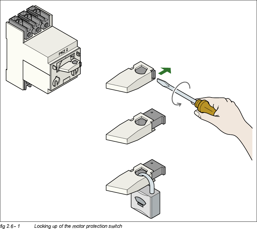
(4)Lock up the system
– Fasten a lock wherever possible, e.g. on the
motor protection switch.
2 Operational Safety Adjustment Instructions SIPLACE HS-50
2.6 Locking Up of Machine and Tagging of Warn Signs Edition 12/00
52
.(<
– Alternatively: Attach warning signs
If a machine can be locked, it must be locked. However, there are situations where in order to
release energy locks cannot be used. In these cases, these machines must be tagged with warn-
ing signs in order to warn employees that the machine is energized for servicing. The tag must be
securely fastened, it must be placed in a position visible to all and it may only be removed by the
person who attached it.
1. Turn the operating lever (1) counter-clockwise.
2. Use the screwdriver to push the locking lug (2) out of the operating lever (1).
3. Secure the operating lever with a padlock (3).