00191374-04.pdf - 第154页
7 Collect & Place Head DLM1 Adjustment Instructions SIPLACE HS-50 7.4 Dynamic Adjustment of the Axes Edition 12/00 154 2VFLOORV FRSH6 HWWLQJV – If the dyna mics of the star a re corre ct, each s ignal wi ll appe…

Adjustment Instructions SIPLACE HS-50 7 Collect & Place Head DLM1
Edition 12/00 7.4 Dynamic Adjustment of the Axes
153
6WDU$[LV
*HQHUDO3UHSDUDWLRQ
Å Start SITEST.
Å Turn on the compressed air.
Å Prepare the measurement setup for the star - axis according to fig 7.4 - 4.
Å Set the oscilloscope according to the table below.
Å Perform a head reference run.
NOTE
Use an RC - filter to record the current curve
Measure the end signal on the adapter board "axis control card", (the lowest BNC socket), with
the switch activated.
Measure the nominal current of the star - axis on the "measuring adapter axis control card current
measure star" (Do not connect GND).
&KHFN3*DLQ
NOTE
An adjustment of the star - axis on the servo amplifier is not possible.
Adjustment parameters are preset by board VC10 Controller. This board is on the axis control card
1, or 2, 3 or 4.
6,7(67
Å Select "C&P Heads" ==> "Select head" ==>
"Axis functions" ==> "Select star - axis" ==> "Continuous run, star" ==> "Input: Waiting
time 500 ms" ==> "Accept".
Å If necessary, press the START button.
7 Collect & Place Head DLM1 Adjustment Instructions SIPLACE HS-50
7.4 Dynamic Adjustment of the Axes Edition 12/00
154
2VFLOORVFRSH6HWWLQJV
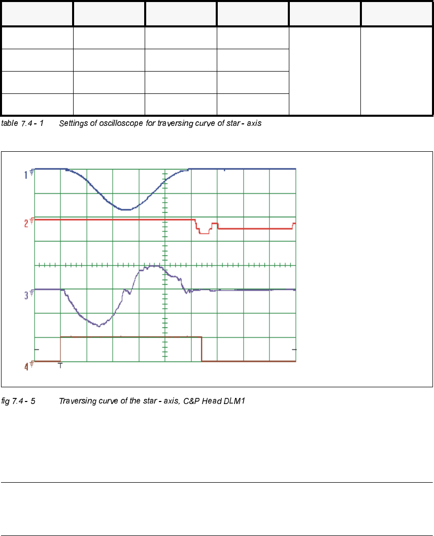
– If the dynamics of the star are correct, each signal will appear as illustrated above.
–Nominal - positioning time:PVPV.
1 cycle = 12000 dgts = 30°degrees.
NOTE
If this setting for the dynamics can not be reached, check the friction blocks on the star and the
mounting of the star while the drive is in its magnetic park position.
&KDQQHO 6LJQDO &RXSOLQJ <'HIOHFWLRQ 7ULJJHU ;'HIOHFWLRQ
CH 1 Vnominal DC 5.0 V/ DIV
CH 4
positive
10% pre
10 ms/ DIVCH 2 deviat. of posit. DC 0.5 V/ DIV
CH 3 nominal current DC 5.0 V/ DIV
CH 4 end signal DC 5,0 V/ DIV
Sollwert /
Vnominal
Positionsabweichung /
deviation of position
Stromsollwert /
nominal current
Endemeldung /
end signal
Adjustment Instructions SIPLACE HS-50 7 Collect & Place Head DLM1
Edition 12/00 7.4 Dynamic Adjustment of the Axes
155
=$[LV
*HQHUDO3UHSDUDWLRQV
Å Start SITEST.
Å Turn on the compressed air supply.
Å Prepare the measurement setup for the star-axis acoording to fig 7.4 - 4.
Å Use standard nozzle 914.
Å Set the oscilloscope according to the table below.
Å Perform a head reference run.
NOTE
Use an RC - filter to record the current curve
In order to measure the actual current on the servo amplifier, connect only the actual current and
no *1'.
Measure the end signal on the measuring adapter of the axis control card, with the switch
activated.
$GMXVWPHQWRI7DFKR
3UHSDUDWLRQ
Å Positioning the gantries, position the z-axis into free space.
6,7(67
Å Select "C&P heads" ==> "Select head" ==>
"Axis functions" ==> "Select z-axis" ==> "Tacho adjustment" ==>
"Edit and accept values: Start position = 0; target position = 685; positioning mode = absolute;
waiting time = 1000".
Å If necessary, press the START button.