00191374-04.pdf - 第150页
7 Collect & Place Head DLM1 Adjustment Instructions SIPLACE HS-50 7.4 Dynamic Adjustment of the Axes Edition 12/00 150 .(< (1) LED: Ready for operati on (2) LED: Enab le outp ut stage (3) LED: I RMS limi t (4)…
Adjustment Instructions SIPLACE HS-50 7 Collect & Place Head DLM1
Edition 12/00 7.4 Dynamic Adjustment of the Axes
149
.(<
TDS 120 A2.5Z = Servo board z-axis
TDS 120 / 1D = Servo board dp - axis
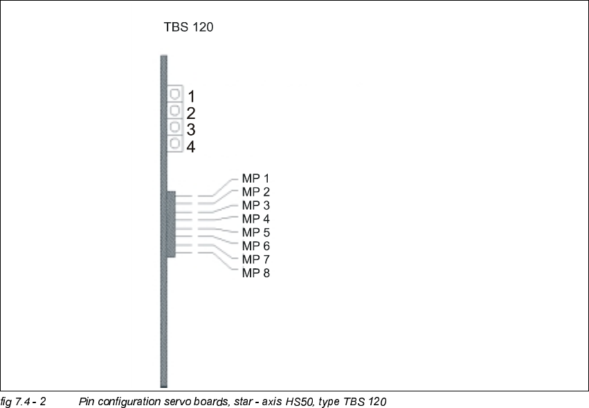
TDS 120 = Pin configuration
LED: Ready for operation
LED: Enable output stage
LED: Effective current limit
LED: Error
Potentiometer: Tacho
Potentiometer: P-Amplification
Ns Speed setpoint value
Ie Setpoint value, power input
Ta Tacho (real tacho voltage)
Is Nominal current (speed controller output)
IA Motor manipulated variable (speed controller output)
li Actual current
Ss Sensor stop signal
0V Amplifier electronic GND
7 Collect & Place Head DLM1 Adjustment Instructions SIPLACE HS-50
7.4 Dynamic Adjustment of the Axes Edition 12/00
150
.(<
(1) LED: Ready for operation
(2) LED: Enable output stage
(3) LED: I
RMS
limit
(4) LED: Error
MP1 = Nominal current "I-S (U)"
MP2 = Nominal current "I-S (W)"
MP3 = Actual current "I-ist (U)"
MP4 = Actual current "I-ist (W)"
MP5 = "U-nominal (U)"
MP6 = "U-nominal (W)"
MP7 = Free
MP8 = Reference potential "0V"
Adjustment Instructions SIPLACE HS-50 7 Collect & Place Head DLM1
Edition 12/00 7.4 Dynamic Adjustment of the Axes
151
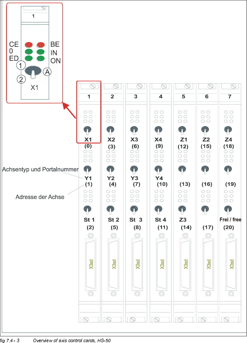
2YHUYLHZRI$[HV&RQWURO&DUGV+6
type of axis and gantry number
adress of axis
'3 '3
'3
'3
CE = Counting error
0 = Zero pulse
ED = End signal
BE = General error, module error
IN = Initialized
ON = Servo ON
(A) Axis enable switch
(1) Servo ON
(2) Servo OFF