00191374-04.pdf - 第140页
7 Collect & Place Head DLM1 Adjustment Instructions SIPLACE HS-50 7.3 Adjustments E dition 12/00 140 $GMXVWPH QW V %HOW7 HQVLRQRIWKH=$[LV Å Attach the mea suring hea d in fron t of the t oothed b elt. …
Adjustment Instructions SIPLACE HS-50 7 Collect & Place Head DLM1
Edition 12/00 7.2 Zero Point Corrections
139
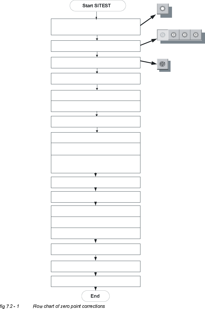
=HUR3RLQW&RUUHFWLRQV
'HWHUPLQDWLRQRI=HUR3RLQW&RUUHFWLRQ6WDU$[LV&ROOHFW3ODFH+HDG
C&P Heads
Axes
Positions
Select star - axis
Select appropriate head
Zero point corrections = 0
edit and accept
Axis reference run
Axis enable
Rotate segment 1 downward,
place gauge for the star, insert pin
Take sleeve out of star position 1
Select the dp-axis and again the star-axis
Note actual position as new
zero point correction
Connect servo
Remove gauge for the star
Insert sleeve
Check zero point corrections
(segment 1, on the bottom)
Save machine data
Axis reference run
7 Collect & Place Head DLM1 Adjustment Instructions SIPLACE HS-50
7.3 Adjustments Edition 12/00
140
$GMXVWPHQWV
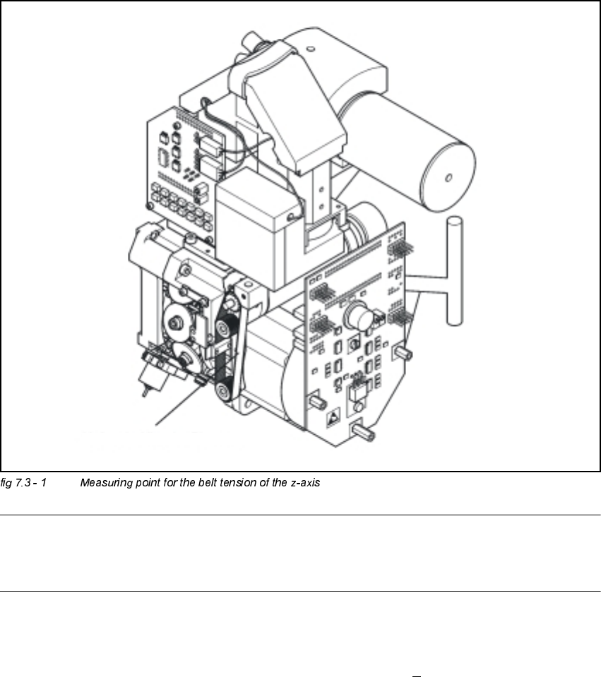
%HOW7HQVLRQRIWKH=$[LV
Å Attach the measuring head in front of the toothed belt.
NOTE
The measuring point of the measuring pin must be in the middle of the two deflection pulleys.
The measuring pin should be at a maximum distance of 2 - 3 mm, from the toothed belt.
Å Strike the toothed belt, to reach a stimulation of vibration of the open ended toothed belt.
Å Stretch the belt over the fastening of the driving motor (compare: service manual) if the
frequency of the belt tension does not reach a value of 280 Hz +
10 Hz.
Å Repeat these instructions until the belt tension is correct.
Messpunkt: Riemenmitte /
measuring point: middle of belt
Adjustment Instructions SIPLACE HS-50 7 Collect & Place Head DLM1
Edition 12/00 7.3 Adjustments
141
6HWWLQJWKHVWRSIRUWKH=D[LV
7RROVDQGHTXLSPHQW
– Set of DIN 911 Allen keys
– Gauge for z axis, from item no. 00331308-01
6HWWLQJV
Å Dismantle the front part of the revolver head as described in section 10.7.2, page 10 - 29 in the
Service manual.
Å Dismantle the star as described in the Service manual.
NOTE
The Z-axis must be correctly mounted (see section. 8.3.1)
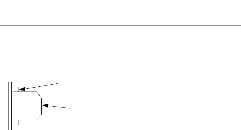
Å Screw the stop piece with both hexagon socket screws M2.5x8 (position 3 in figure 8.3.2)
tightly to the drive belt, so that the clamping device is firmly fixed between the teeth of the drive
belt. (see fig.)
Å Carefully raise the Z-axis by hand, until the snap jaws (Pos. 5) are at least above the raceway
(Pos. 6).
Å Put the raceway with the Z-axis gauge into the position marked A.
Å Unscrew the hexagon socket screw of the stop piece. (Pos. 1 in fig. 8.3.2)
Å Insert the stop piece in to the stopping face until contact is made.(Pos. 2 in fig. 8.3.2)
Å Fix the stop piece to the hexagon socket screw M2x4.
Do not use a ball-end-allen wrench.
drivebelt tooth
Clamping device between the
teeth of the drive belt