00191374-04.pdf - 第37页
Adjus t ment In str uc tio ns SI PLA CE HS- 50 2 Operational Safety Edition 12/00 2.2 Safety Equipm ent 37 – T he 230 V operat ing voltage f or the liftin g table mot ors. – T he se rvo uni t will re ceiv e a "Ser v…
2 Operational Safety Adjustment Instructions SIPLACE HS-50
2.2 Safety Equipment Edition 12/00
36
– Channels 2 and 3 of the protective contactor combination (PCC).
If the safety circuit is closed, 24 VDC are present at channels 2 and 3 of the PCC.
In addition to the power control LED, the two green LEDs for channels 2 and 3 are illuminated.
6WUXFWXUHRIWKH6LJQDO&LUFXLW
The six signalling contacts for the covers are connected in parallel and form the "Cover signal"
circuit. If you open one or more covers, the contacts close - and the 24 V signal reaches the
CAN BUS signalling that one of the covers is open.
The two signalling contacts of the EMERGENCY STOP buttons are connected in parallel and form
the "EMERGENCY STOP button" circuit. If an EMERGENCY STOP button is activated, a
24 V signal is sent to the CAN BUS signalling that one of the EMERGENCY STOP buttons has
been pressed.
The four signalling contacts of the push button flaps are connected in parallel. They form the "flaps
signal" circuit. If one or more flaps is raised, a 24 V signal is sent to the CAN BUS signalling that
one of the cover flaps is not closed.
The four signalling contacts of the component tables are connected in series and form the
"Component table signal" circuit. If a component table is missing, a 0 V signal is sent to the CAN
BUS. If all the tables are connected, the signal is approximately 16 V.
)XQFWLRQDO'HVFULSWLRQRIWKH6DIHW\&LUFXLW
The following conditions must be fulfilled before the placement system can be started or
operated:
– All four component tables must be docked on and connected.
– All covers - four over the gantries, one over the PCB input belt, and one over the output belt -
must be closed.
– Both EMERGENCY STOP buttons must be released.
– All four flaps over the push buttons for lifting and lowering the component tables must be
closed.
– The minimum operating pressure must have been reached.
– The software must have been enabled, and the safety circuit activated as a result.
– The power supply must be sending 24 V to the START buttons and the protective contactor
combination.
– If one of the START buttons will be activated then, the protective contactor combination (PCC)
will switch and activate the following components:
– The 200 V link voltage for the servo amplifier for the gantry axes.
– The 100 V link voltage for the star axes.
Adjustment Instructions SIPLACE HS-50 2 Operational Safety
Edition 12/00 2.2 Safety Equipment
37
– The 230 V operating voltage for the lifting table motors.
– The servo unit will receive a "Servo enable" signal for the servo amplifier.
– The 34 V operating voltage is switched to the component tables.
– The 24 V operating voltage is switched to the tape cutting units.
The machine is now ready for operation.
2 Operational Safety Adjustment Instructions SIPLACE HS-50
2.2 Safety Equipment Edition 12/00
38
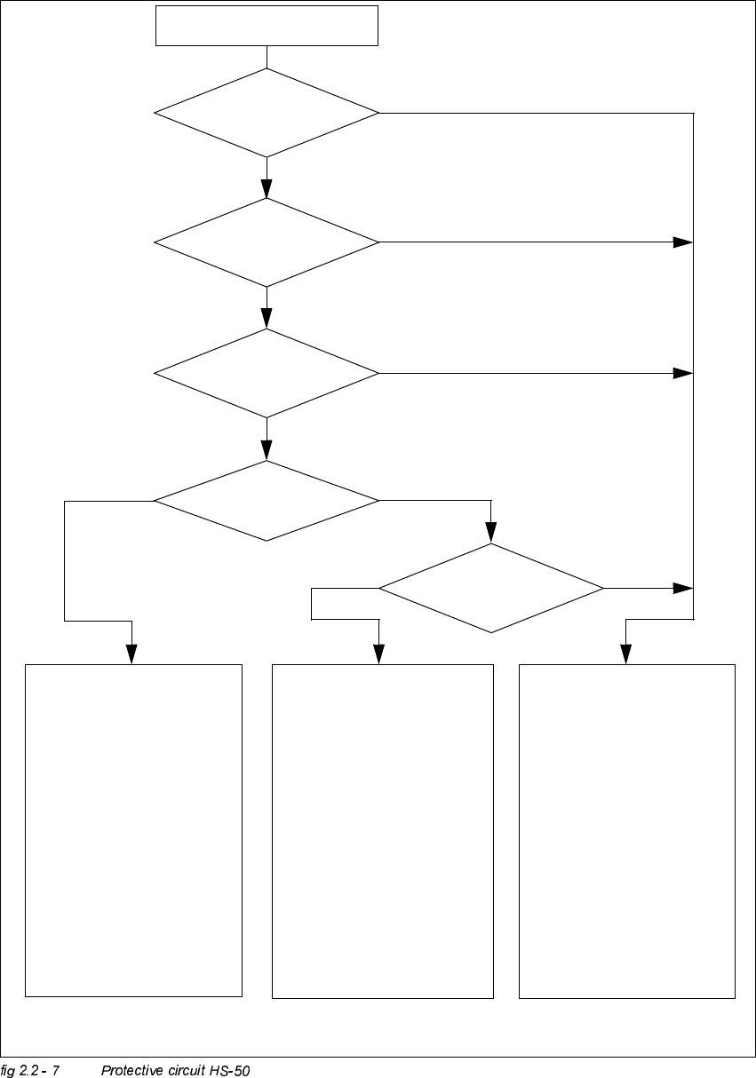
Compressed air
min. 5.0 bar?
No
START - button pressed
EMERGENCY STOP button
pressed?
Protective cover open?
Key switch
closed (Position I)?
No
Component table safety circuit
interrupted?
Yes
No
No
Yes
Yes
No
$FWLYH
PCC*) Yes
9ROWD J H
Y-axis 200 V
X-axis 200 V
Star-axis 100 V
Dp-axis 30 V
Z-axis 30 V
$FWLYH
PCB conveyor Yes
PCB clamping Yes
Width adjustment Yes
PCB stopper Yes
Lifting table Yes
Tape cutting unit Yes
Yes
$FWLYH
PCC*) No
9R O WDJH
Y-axis 0 V
X-axis 0 V
Star-axis 6 V
Dp-axis 30 V
Z-axis 30 V
$FWLYH
PCB conveyor Yes
PCB clamping No
Width adjustment Yes
PCB stopper No
Lifting table No
Tape cutting unit No
$FWLYH
PCC*) No
9ROWD J H
Y-axis 0 V
X-axis 0 V
Star-axis 10 V
Dp-axis 30 V
Z-axis 30 V
$FWLYH
PCB conveyor No
PCB clamping No
Width adjustment No
PCB stopper No
Lifting table No
Tape cutting unit No
*) PCC protective contactor combination
Yes