DEK INFINITY USER MANUAL.pdf.pdf - 第135页
INFINITY 6(735()(5( 1&(6 35()(5(1& (6 Soft ware Ver sion 7 User Manual 2.9 Change Mode Option Sets the screen change mode, options are: NOTE The dual shuttle option is only r elevant on a machine with a dual shu…
INFINITY
6(735()(5(1&(6
35()(5(1&(6
2.8 User Manual Software Version 7
The optional External Product Barcode Reader provides a generic bar code
interface for the capturing by GEM and SPC of a product bar code before the
product is passed to the printer. Use of the reader enables a host program to
decide on the action to be taken for this product and provides a method for SPC
to log product details for tracking.
The DEK printer acts as a dumb receiver of barcode data and provides no set up,
configuration or triggering information for the barcode reader.
Compatible Bar
Code Reader
The printer has been designed to operate with a SICK Model CLV 212 Bar code
reader.
Options The External Barcode parameter options are:
If the bar code reader is set to Disabled, COM 1 is setup as per previous versions
of software and enabled to accept serial host comms.
If the bar code reader is set to Enabled, COM 1 is set to use the external bar code
reader and the option Serial Comms is removed from the Comms Protocol
parameter in the Set Preferences menu.
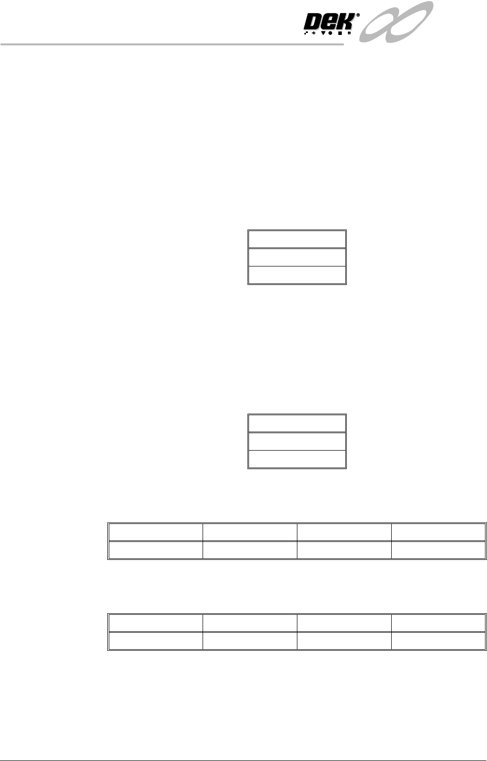
Pressure H/W Used when pressure feedback hardware is fitted, options are:
ProFlow Contact
Position
This parameter sets the height of the ProFlow printhead so that it just touches
the stencil surface.
ProFlow Down
Stop Position
This parameter pre-tensions the squeegee suspension springs to provide
ProFlow with a zero pressure datum.
Options
Enabled
Disabled
Options
Not Fitted
Fitted
Minimum Maximum Increment Default
- 10mm +10mm 0.1mm 0.0mm
Minimum Maximum Increment Default
- 10mm +10mm 0.1mm 0.0mm
INFINITY
6(735()(5(1&(6
35()(5(1&(6
Software Version 7 User Manual 2.9
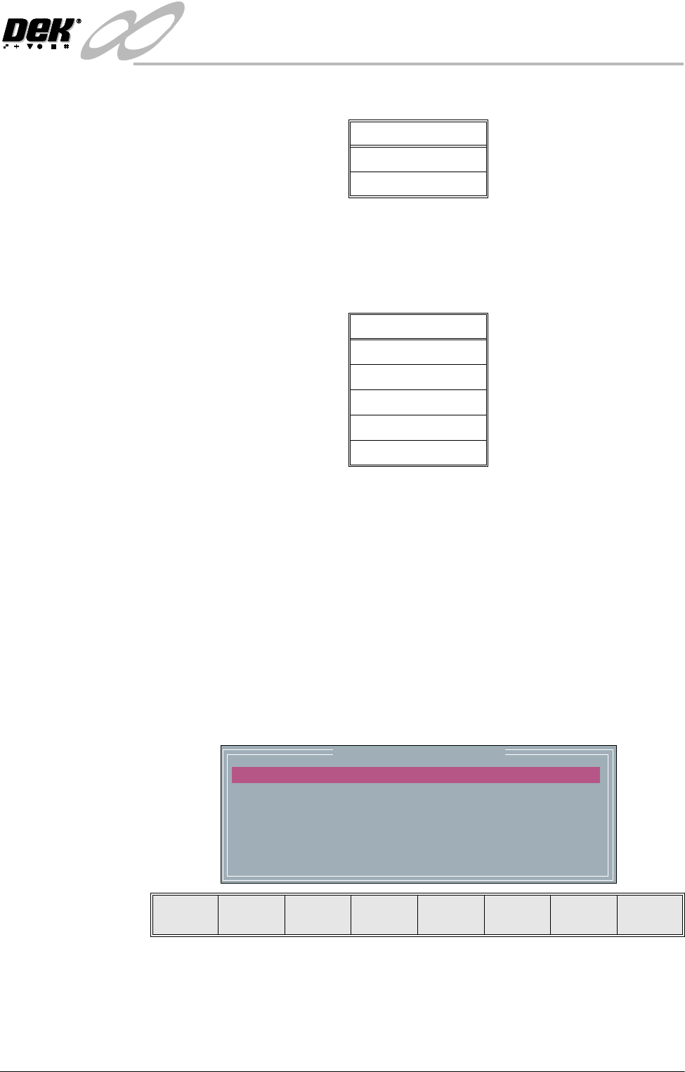
Change Mode
Option
Sets the screen change mode, options are:
NOTE
The dual shuttle option is only relevant on a machine with a dual shuttle unit
fitted.
Screen Size Sets the screen size frame, these options are:
With Screen Library enabled the printer is provided with detailed screen dimen-
sional information from a ‘read only’ library. This information is stored within
the machine configuration and product files.
Once selected in Set Preferences, detailed frame dimensions are provided to the
printer. In Edit Current Process Parameters, the parameter Image Data provides
comprehensive location and mesh details to the printer.
To enable screen library files carry out the following:
1. Highlight Screen Size in the Set Prefs page.
2. Using Incr. or Decr. select Screen Library.
Edit Data is now available on the menu bar.
3. Select Edit Data, the following window and menu bar is displayed:
Use Incr. or Decr. to select the required Screen Type. If no valid screen
library files are found, the default file DEK 265 Central Image is displayed.
Use the Next or Previous to select and Incr. or Decr. to modify the screen
frame parameters as required.
Options
Manual
Dual Shuttle
Options
265
Screen Library
Fuji
249
Sanyo
mm
mm
mm
mm
mm
mm
Screen Frame Configuration
XXX
XXX
XXX
XXX
XXX
XXX
SCREEN TYPE
SCREEN LENGTH
SCREEN WIDTH
FRAME FRONT
FRAME REAR
FRAME LEFT
FRAME RIGHT
DEK 265 CENTRAL IMAGE
Next Previous Incr. Decr. Exit
INFINITY
6(735()(5(1&(6
35()(5(1&(6
2.10 User Manual Software Version 7
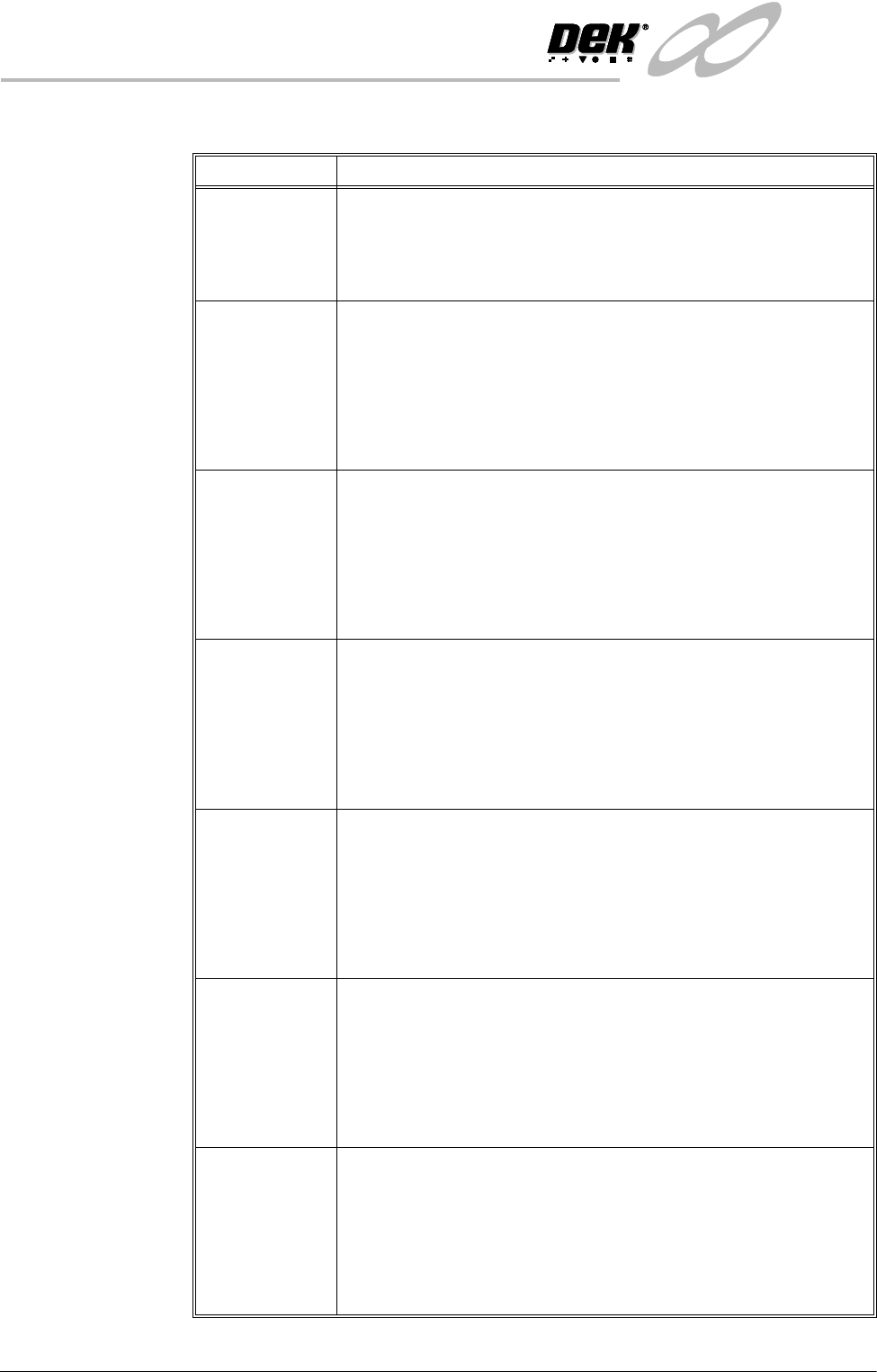
The screen library menu parameters are defined in the table below:
Parameter Definition
Screen Record ID The identity of the screen type library record containing a text string that
matches the Screen Type selected.
Format Maximum 32 character text string
Default DEK 265 Central Image
Screen Length This parameter sets overall dimension front to rear of the screen frame or
adaptor.
Minimum 550mm
Maximum 860mm
Increment 0.1mm
Default 736.6mm
Screen Width This parameter sets the overall dimension left to right of the screen frame
or adaptor.
Minimum 580mm
Maximum 736.6mm
Increment 0.1mm
Default 736.6mm
Frame Front This parameter sets the distance between the outer edge of the screen
frame or adaptor and the inner edge of the frame, at the front of the frame.
Minimum 20mm
Maximum Screen Length - 250mm
Increment 0.1mm
Default 38.1mm
Frame Rear This parameter sets the distance between the outer edge of the screen
frame or adaptor and the inner edge of the frame, at the rear of the frame.
Minimum 20mm
Maximum Screen Length - 250mm
Increment 0.1mm
Default 38.1mm
Frame Left This parameter sets the distance between the outer edge of the screen
frame or adaptor and the inner edge of the frame, at the left of the frame.
Minimum 20mm
Maximum Screen Length - 250mm
Increment 0.1mm
Default 38.1mm
Frame Right This parameter sets the distance between the outer edge of the screen
frame or adaptor and the inner edge of the frame, at the right of the frame.
Minimum 20mm
Maximum Screen Length - 250mm
Increment 0.1mm
Default 38.1mm