DEK INFINITY USER MANUAL.pdf.pdf - 第43页
INFINITY 0$&+,1 (352*5 $00,1* 67$*(& '( ',&$7(' 722/,1* Soft ware Ver sion 7 User Manual 1.41 5. Fit the head prop. 6. Press Confirm (F1). 7. Fit the tooli ng tower to the manual tooling…
INFINITY
0$&+,1(352*5$00,1*
67$*(&'(',&$7('722/,1*
1.40 User Manual Software Version 7
STAGE 6C - DEDICATED TOOLING
WARNING
BOARD CLAMPS. EXTREME CARE MUST BE EXERCISED WHEN WORKING IN
THE TOOLING AREA OF THE MACHINE TO AVOID INJURY. THE FOILS ON THE
FRONT AND REAR BOARD CLAMPS ARE VERY SHARP.
CAUTION
BOARD CLAMPS. Care must be taken to ensure that the board clamps
are not damaged when removing or replacing tooling.
1. Select Change Tooling (F6).
2. Select Full Width (F5). The message ‘Checking for a board on the belts’
is displayed. Whilst the rear rail is moving the following message ‘Rail
Moving...’ is displayed.
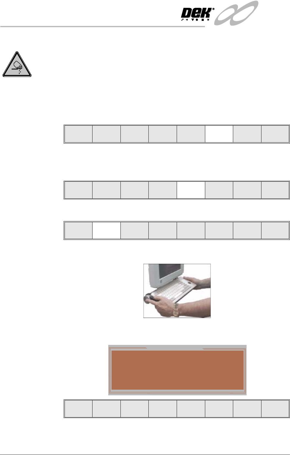
3. Select Raise Head (F2).
4. Raise the printhead using two button control.
The following window and menu bar is displayed:
Mode
Load
Data
Edit
Data
Setup
Squeegee
Change
Screen
Change
Tooling
Change
Language
Exit
Adjust
Raise
Head
Remove
Cleaner
Board
Stop
Full
Width
Load
Width
Print
Height
Exit
Adjust
Raise
Head
Remove
Cleaner
Board
Stop
Board
Width
Load
Width
Print
Height
Exit
Hazardous Operation
The head must be propped while it is
raised
Insert the Head Prop.
Confirm
Lower
Head
INFINITY
0$&+,1(352*5$00,1*
67$*(&'(',&$7('722/,1*
Software Version 7 User Manual 1.41
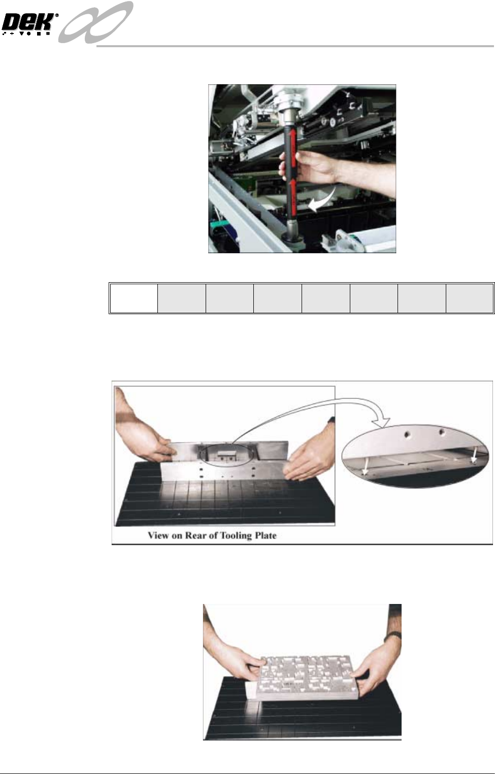
5. Fit the head prop.
6. Press Confirm (F1).
7. Fit the tooling tower to the manual tooling plate. Ensure the dowels on the
front edge of the tooling tower base are correctly seated in the holes in the
front edge of the manual tooling plate.
8. Verify the plate assembly orientation and fit the assembly to the tooling
tower. Ensure the dowels of the plate assembly are correctly seated in the
holes in the tooling tower.
Confirm
Lower
Head
INFINITY
0$&+,1(352*5$00,1*
67$*(&'(',&$7('722/,1*
1.42 User Manual Software Version 7
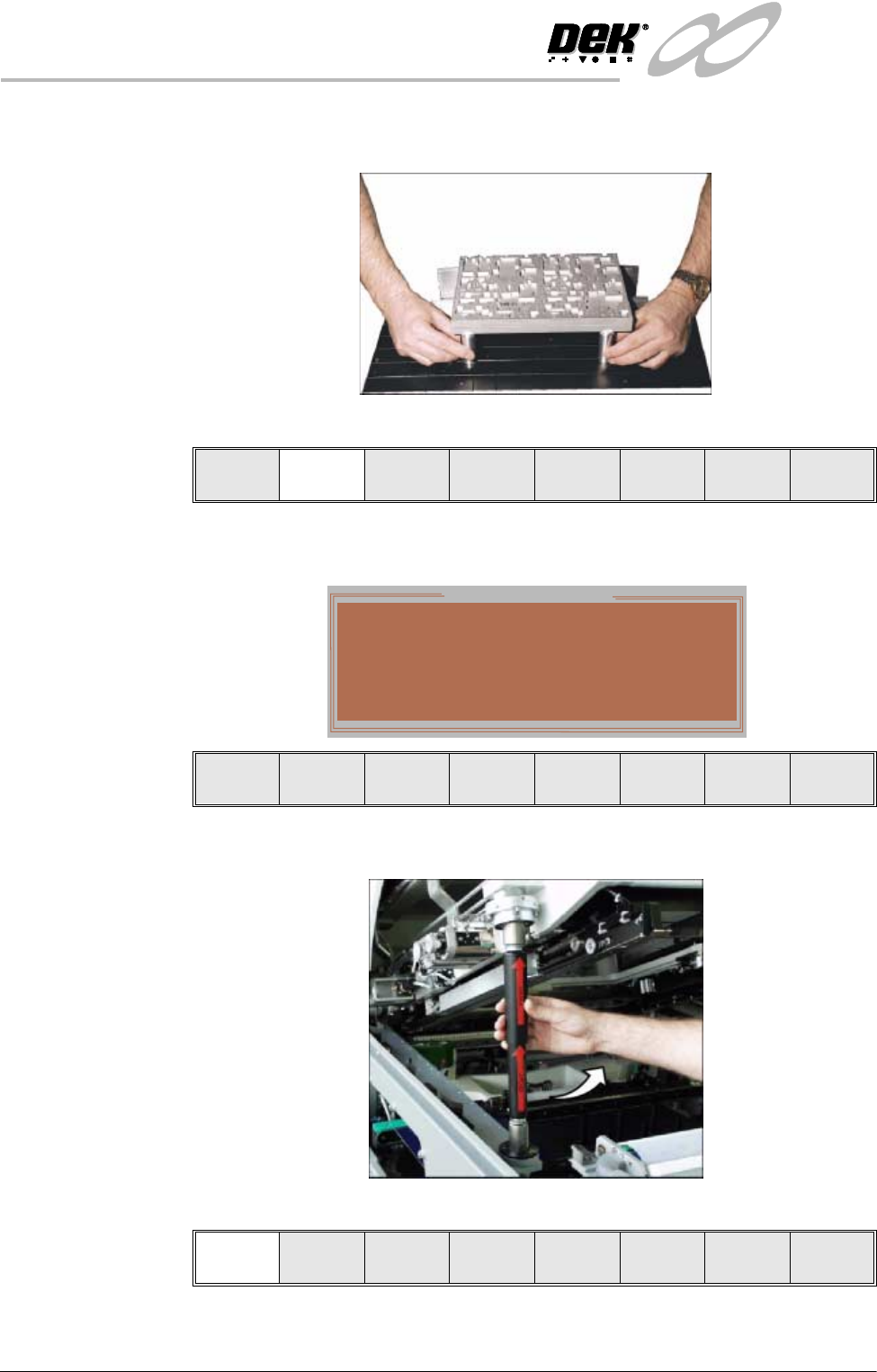
9. If required, slide additional magnetic pins beneath the plate assembly to fully
support it when printing wide boards.
10.Select Lower Head (F2).
The following window and menu bar is displayed:
11. Remove the Head Prop.
12.Select Confirm (F1).
13.Lower the printhead using two button control.
Adjust
Lower
Head
Board
Clamps
Set
Stop
Hazardous Operation
The head is about to be lowered
Remove the Head Prop and confirm that
everyone is standing clear.
Confirm Cancel
Confirm Cancel