00197461-01_AI_Portaltausch_X-Serie_S_INTERN_de_en.pdf - 第57页
Installation Removing the Gantry Gantry Exchange Portaltausch 57 Removing the pin picker ► If the Smart Pin Support option is fitted, remove the pin picke r. Read the as sembly instructions "Smart Pin Support - X-Se…
Installation
Removing the Gantry
56 Gantry Exchange Portaltausch
3.2
3.2 Removing the Gantry
Removing the Gantry
To remove the gantry, perform the following steps:
Removing the cover on the hood guide
Dismantling the side cover
Removing the placement head
► Dismantle the placement head. Read the service manual for your machine first.
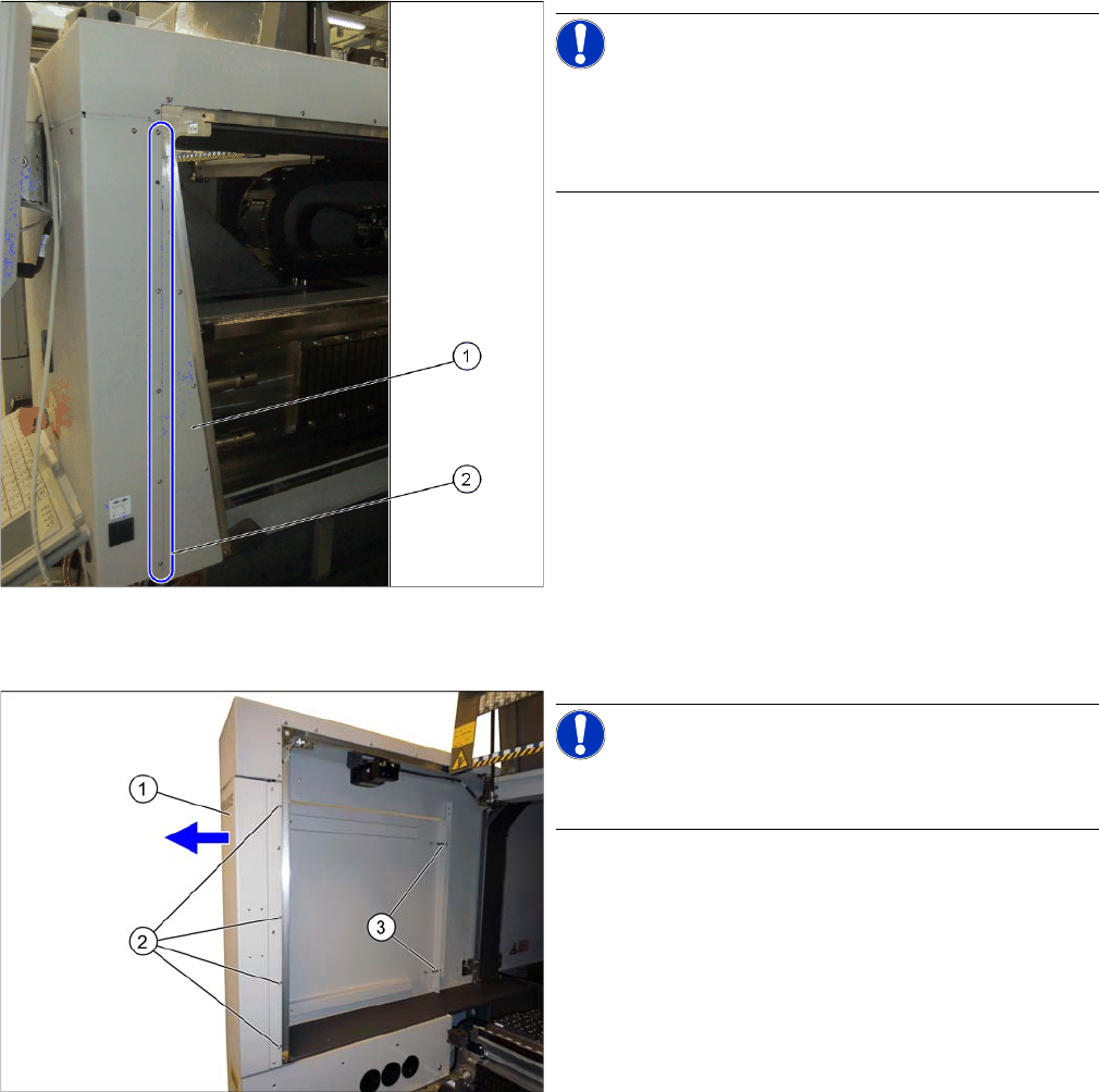
NOTICE!
As an option, the SIPLACE X-Series S machines have
covers on the hood guides. If your machine has a cover
on the hood guide, you will need to remove this cover on
the hood guide.
► Loosen the screws (2) fastening the cover on the
hood guide (1).
► Pull the cover on the hood guide off the machine.
NOTICE!
If there is a service flap fitted at the relevant location, this
item does not apply.
► Loosen the screws (2) fastening the side cover (1)
and pull this off the pins (3).
Installation
Removing the Gantry
Gantry Exchange Portaltausch 57
Removing the pin picker
► If the Smart Pin Support option is fitted, remove the pin picker. Read the assembly instructions
"Smart Pin Support - X-Series S" [00197394-xx].
Removing the buffer
Removing the magnets
NOTICE
Removal
► Unplug all hoses and cables to the pin picker
► Mark the position of any opened cable ties.
► Loosen the three screws fastening the pin picker.
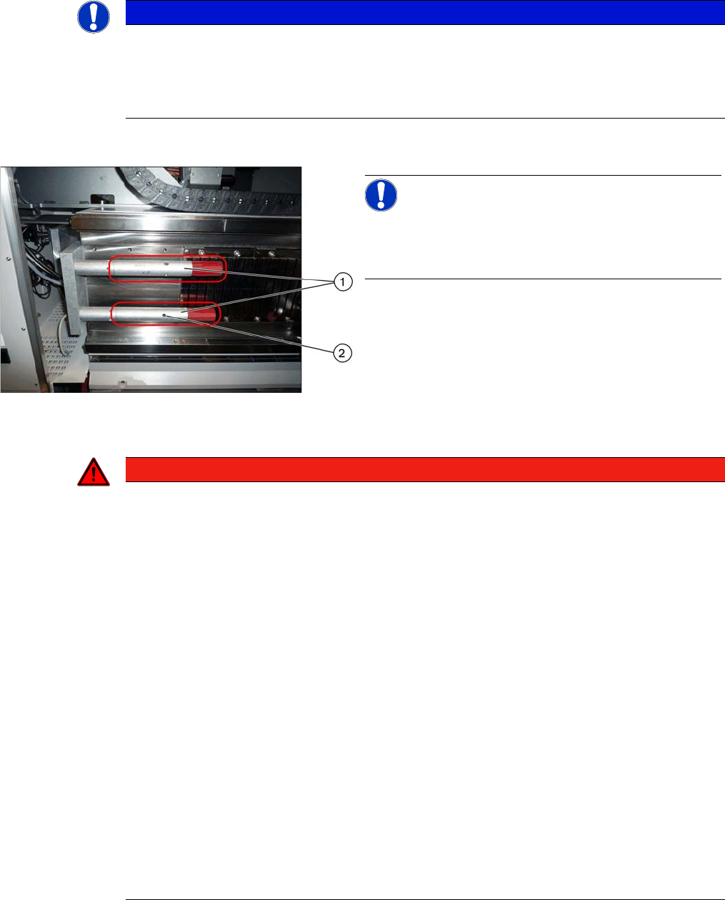
NOTICE!
Location 1 and 3 at X3 S, X4 S:
Only short buffers are fitted here. These do not need to
be removed.
► Remove the two buffers (1). Insert a suitable tool into
the hole provided (2) and unscrew the buffer.
DANGER
Risk of trapped limbs - observe the safety instructions!
The magnets are very powerful. There is a risk of body limbs being trapped.
► Please make sure you observe the applicable section "1.1.3 Safety Instructions for Working
with Strong Magnetic Fields (internal)" [ ➙ 42].
► The magnets attract each other and there is a risk of fingers setting trapped between the
magnets.
► Observe the magnet pole direction "N". The magnet pole direction "N" must be on the same
side for all magnets.
► Place the magnet on the machine frame and push the magnet gently into the mounting po-
sition.
► Only ever remove one magnet at a time and place it on its own in suitable packaging.
► Keep a safe distance between the individual magnets.
► Never place the magnets down on a work surface without securing them. When storing the
magnets, always use the prescribed packaging (box lid for magnet 150x64-128 [03105100-
xx]).
► Keep emergency protective equipment ready in case an accident occurs:
Plastic wedge, 65 x 180 mm [03097870-xx]
Copper hammer, 750 g [03097897-xx]
► The copper hammer and wedges are used in case of accidents, to separate the magnets.
► When working with magnets, enlist the help of an additional person.
Installation
Removing the Gantry
58 Gantry Exchange Portaltausch
► Loosen in sequence the screws fastening each magnet, and then remove the magnet.
Disconnecting the trailing cable and hoses
In order to easily remove the gantry, you first need to re-
move several magnets. The quantity to be removed de-
pends on the machine and location:
X3 S, X4 S – location 1, 3:
Minimum of five magnets
X3 S, X4 S – location 2/4 and X4i S:
Minimum of three magnets
WARNING
Powerful magnetic fields!
Risk of injuries and/or damage to property from powerful magnetic fields.
► When working on the magnets, observe the safety instructions 00195600-xx about working
with powerful magnetic fields!
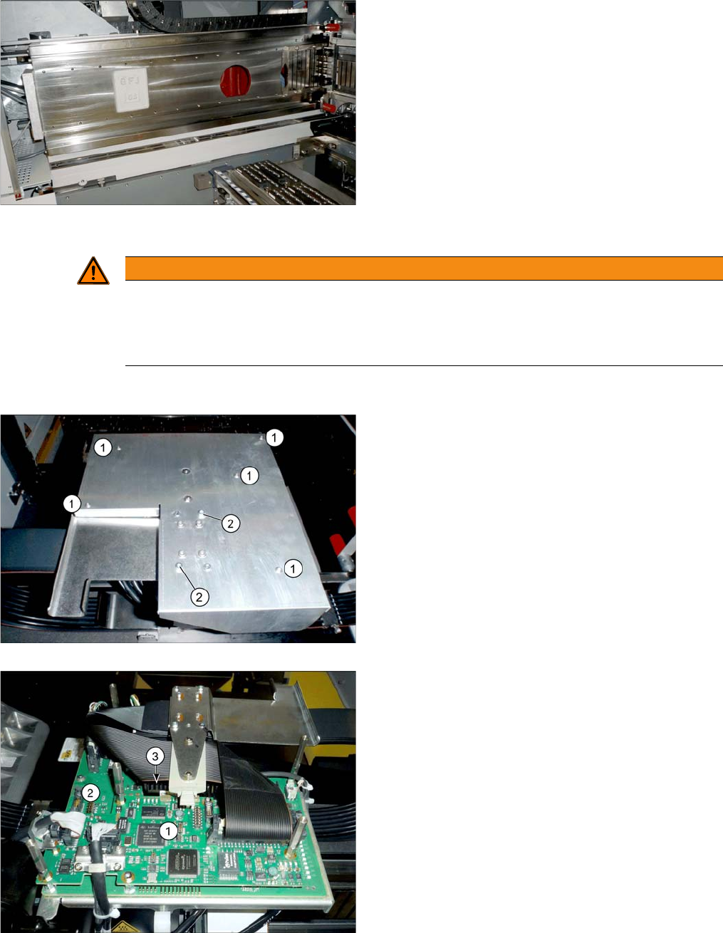
1. Five fastening screws (not sealed)
2. Two fastening screws (with sealing varnish)
► If there is a board cover present, dismantle this. You
need to loosen the fastening screws for this at(1)
and (2).
Boards on the gantry
1. Vision board spread spectrum
2. Head interface
► Unplug all trailing cable cables from the head inter-
face. You may want to mark their positions, to make
clear assignment easier later on (see also "4.1 De-
scription of Boards" [ ➙ 69]).