00197461-01_AI_Portaltausch_X-Serie_S_INTERN_de_en.pdf - 第72页
Appendix Description of Boards 4.1.3 Head interface C700X-R [03055070- xx] 72 Gantry Exchange Portaltausch 4.1.3 4 . 1 . 3 H e a d in t e r f a c e C 7 0 0 X - R [ 0 3 0 5 5 0 7 0 - x x ] Head interface C7 00X-R [0305507…
Appendix
4.1.2 Head interface C700X-L [03055068-xx] Description of Boards
Gantry Exchange Portaltausch 71
7-segment display V2 [03055067-05]
7-segment display V12 [03055067-05]
Dip switch S1 [03055067-05]
Display Status Description
Decimal point Flashes HCU2 OK
Display Status Description
Decimal point Flashes HCU1 OK
Switch Status Signal name Description
Gantry 1 Gantry 3
S1.1 OFF/ON Gantry_ID0 OFF OFF
S1.2 OFF/ON Gantry_ID1 OFF ON
S1.3 OFF COM_BOOT_HCU ON: set HCU to bootstrap mode
RES1 to ON. BOOT to ON. RES1 OFF. BIOS
download via external interface possible.
S1.4 OFF RESET_HCU2 ON: Reset HCU2
S1.5 OFF RESET_HCU1 ON: Reset HCU1
S1.6 OFF FAN Not used
S1.7 OFF DCDC_OFF DC/DC converter
Standard OFF. A reset (ON) is possible if not
all voltages are present (power fail LEDs on
the basic adapter board)
S1.8 OFF HCU_1_2 Not used
Appendix
Description of Boards 4.1.3 Head interface C700X-R [03055070-xx]
72 Gantry Exchange Portaltausch
4.1.3
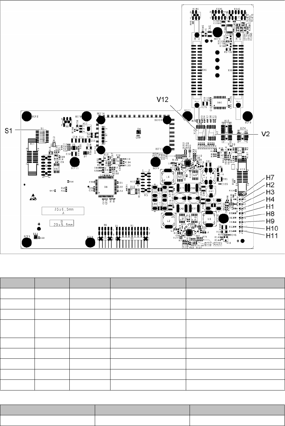
4.1.3 Head interface C700X-R [03055070-xx]
Head interface C700X-R [03055070-xx]
03055069-05
LED [03055069-05]
7-segment display V2 [03055069-05]
LED Color Status Signal name Description
H1 RD - HCU1_LED_ERROR Not used
H2 RD ON POWERFAIL_BASE PowerFail from power supply
H3 RD ON EMERGENCY-STOP_3V Emergency stop: hood opened
H4 RD ON POWERFAIL_LOCAL_3V PowerFail local: errors at 1.5V,
3.3V, 5V, +15V, -15V
H7 RD ON X_TEMP_SENS X motor: temperature too high
H8 RD - HCU2_LED_ERROR Not used
H9 RD - HCU1_LED_READY Not used
H10 RD - HCU2_LED_READY Not used
H11 GN ON LED_5V_OK FPGA OK
Display Status Description
Decimal point Flashes HCU2 OK
Appendix
4.1.4 Vision board spread spectrum HCU [03067289-xx] Description of Boards
Gantry Exchange Portaltausch 73
7-segment display V12 [03055069-05]
Dip switch S1 [03055069-05]
4.1.4
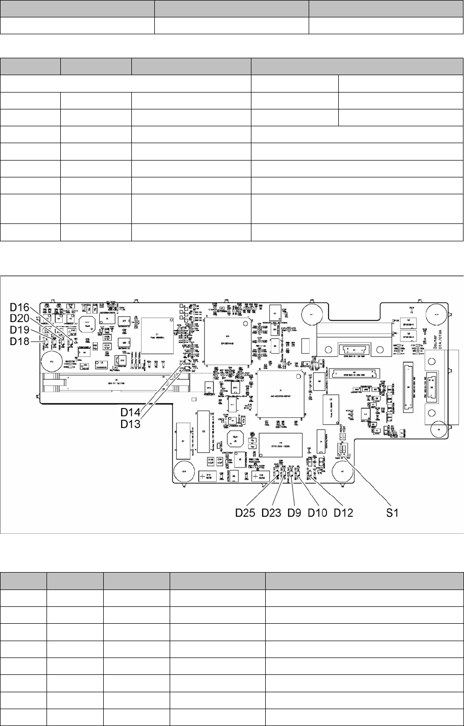
4.1.4 Vision board spread spectrum HCU [03067289-xx]
Vision board spread spectrum HCU [03067289-xx]
03067289-02
LED [03067289-02]
Display Status Description
Decimal point Flashes HCU1 OK
Switch Status Signal name Description
Gantry 2 Gantry 4
S1.1 OFF/ON Gantry_ID0 ON ON
S1.2 OFF/ON Gantry_ID1 OFF ON
S1.3 OFF COM_BOOT_HCU ON: set HCU to bootstrap mode
S1.4 OFF RESET_HCU2 ON: Reset HCU2
S1.5 OFF RESET_HCU1 ON: Reset HCU1
S1.6 OFF FAN Not used
S1.7 OFF DCDC_OFF ON: Reset, when not all the voltages are pres-
ent
S1.8 OFF HCU_1_2 Not used
LED Color Status Signal name Description
D9 GN ON LED_XC_OK RUN
D10 RD ON LED_XC_ERR ERROR
D12 RD ON XC_RESET RESET
D13 GN ON IO/LVDS51P PCB camera active
D14 GN ON IO/LVDS51N CO camera active
D16 GN ON P12VCAM_I +12VDC for camera
D18 GN ON P5VCAM +5VDC for camera
D19 GN ON P2.5VCAM + 2.5 VDC for camera