00197461-01_AI_Portaltausch_X-Serie_S_INTERN_de_en.pdf - 第63页
Installation Converting Attached Parts Gantry Exchange Portaltausch 63 Head adapter HCU with protective plate ► Read the relevant section in the service manual. The PCB Camera ► Read the relevant section in the service m…
Installation
Converting Attached Parts
62 Gantry Exchange Portaltausch
3.3
3.3 Converting Attached Parts
Converting Attached Parts
The following parts must be attached as new parts or taken off the old gantry and attached to the new
one.
Fitting the scale
► Fit the scale to the gantry, and also read the section "Replacing the Scale" in the service manual for
HF/X-Series (internal version) [00195654-xx].
Incremental encoder
► Dismantle the incremental encoder from the old gantry. Read the relevant section in the service man-
ual.
Head interface and Vision Board Spread Spectrum
► Read the relevant sections in the service manual.
Temperature sensor
► Read the relevant section in the service manual.
We recommend that you fasten the corresponding cable with cable ties, after installation. Fasten it
until then with a cable tie to the gantry.
Buffer
► Dismantle the buffer and fit this to the new gantry.
NOTICE
Recommendations
We recommend that you take the attached parts off the old gantry and fit them to the new gantry
when the gantry is outside the machine.
It is helpful to place the old and new gantries next to one another and to fit a part onto the new
gantry, as soon as you have taken it off the old one. This makes it easier to clearly allocate
screws etc to the right place.
NOTICE
Do not fit the incremental to the new gantry yet.
► We recommend that you only fit the incremental encoder once you have fitted the new gan-
try in the machine.
CAUTION
Plastic covers
► Check whether the plastic covers are present on connector X1 of the head interface.
CAUTION
Heat-conductive rubber
► Take care of the heat-conductive rubber under the board.
NOTICE
Threaded rods
► If required, use two counterlocked M8 nuts, in order to loosen the threaded rods still in the
thread.

Installation
Converting Attached Parts
Gantry Exchange Portaltausch 63
Head adapter HCU with protective plate
► Read the relevant section in the service manual.
The PCB Camera
► Read the relevant section in the service manual.
Hose on the silencer
► Disconnect the hose on the silencer from the old gantry and fit it onto the new gantry.
CAUTION
Connectors, HCU
► Make sure that the head adapter board is connected to the head interface via a press-fit
connection from below.
► Do not loosen the two screws fastening the HCU.
CAUTION
Loctite 241
► Secure the screws fastening the PCB camera with Loctite 241.
Installation
Installing the Gantry
64 Gantry Exchange Portaltausch
3.4
3.4 Installing the Gantry
Installing the Gantry
Fitting the gantry
Fitting the incremental encoder and motor cable
► Fit the incremental encoder. For details, refer to the service manual.
► Pull the protective foil off the scale.
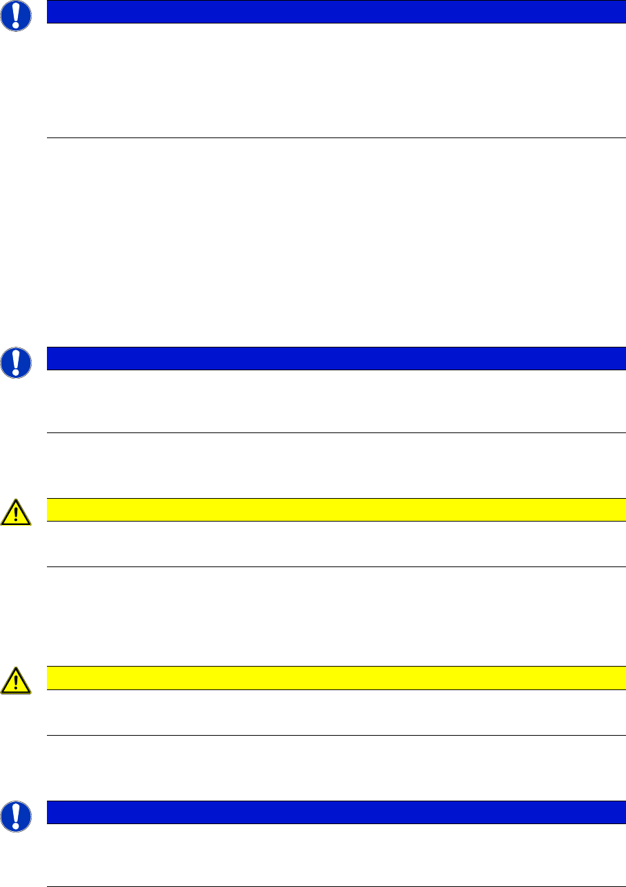
► If there is a corresponding label on the head plate, re-
move this label (1).
► Check the contact surfaces (1) on the new gantry and
trim these if needed with a dressing stone.
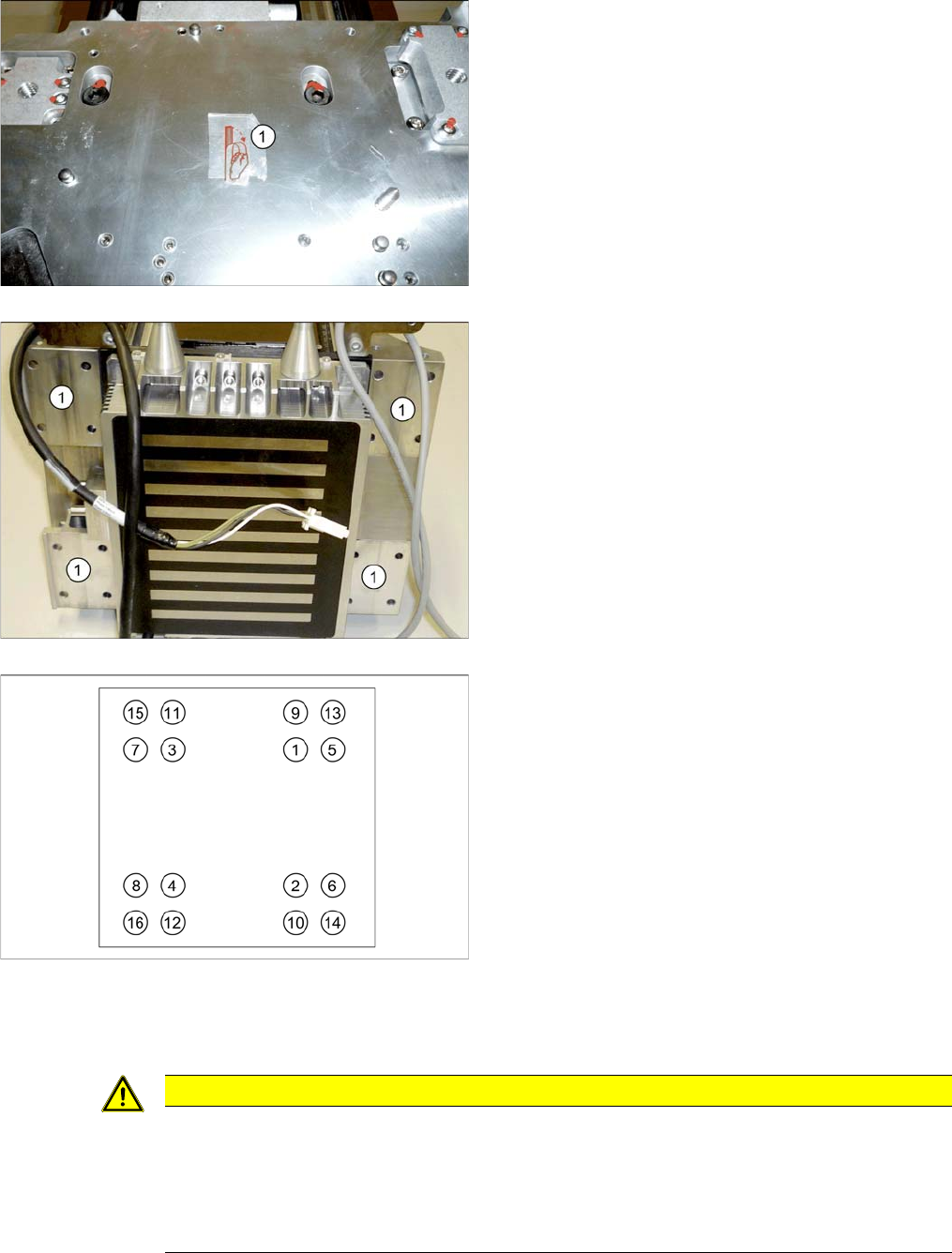
► Carefully lift the gantry into the machine and fasten it.
When inactive, one screw at the top (e.g. (9)) is
enough to hold the gantry.
► While doing this, press the gantry downwards, onto
the contact surface of the guide trolley.
► Tighten the screws with a torque of 9.5 Nm. Proceed
as shown, in the order from (1) to (16).
▪ M6x14 screws are used on the top of the gantry.
▪ M6x22 screws are used at the bottom of the gantry.
▪ Replace the threaded bolt with a screw.
CAUTION
Clean the read surface, air gap, cable duct
► Clean the reading surface of the incremental encoder with a cloth and ethanol or with a Q
tip.
► Fit the incremental encoder with a gap of 0.8 mm to the scale.
► Make sure that the axes can be moved without damaging the cables.