00197461-01_AI_Portaltausch_X-Serie_S_INTERN_de_en.pdf - 第70页
Appendix Description of Boards 4.1.2 Head interface C700X-L [03055068- xx] 70 Gantry Exchange Portaltausch 4.1.2 4 . 1 . 2 H e a d in t e r f a c e C 7 0 0 X - L [ 0 3 0 5 5 0 6 8 - x x ] Head interface C700X-L [03055068…
Appendix
4.1.1 Gantry interface Description of Boards
Gantry Exchange Portaltausch 69
4
4 Appendix
Appendix
4.1
4.1 Description of Boards
Description of Boards
4.1.1
4.1.1 Gantry interface
Gantry interface
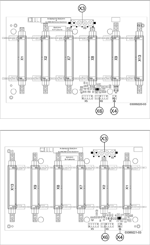
Gantry interface [03089220-03]:
This gantry interface is used for gantries 1 and 3.
X3) Y axis motor power
X4) Y axis motor temperature sensor
X6) Y axis incremental encoder
Gantry interface [03089221-03]:
This gantry interface is used for gantries 2 and 4.
X3) Y axis motor power
X4) Y axis motor temperature sensor
X6) Y axis incremental encoder
Appendix
Description of Boards 4.1.2 Head interface C700X-L [03055068-xx]
70 Gantry Exchange Portaltausch
4.1.2
4.1.2 Head interface C700X-L [03055068-xx]
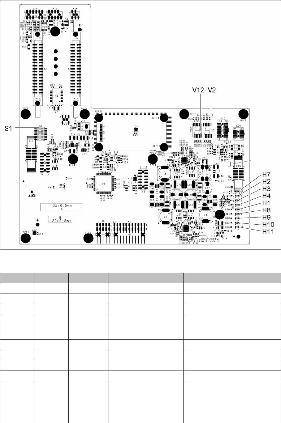
Head interface C700X-L [03055068-xx]
03055067-05
LED [03055067-05]
LED Color Status Signal name Description
H1 RD - HCU1_LED_ERROR Not used
H2 RD ON POWERFAIL_BASE PowerFail from power supply
H3 RD ON EMERGENCY-STOP_3V Emergency stop or cover opened
H4 RD ON POWERFAIL_LOCAL_3V Power fail local: monitors voltages
generated by DC/DC converter
+15V, -15V, +5V, +3.3V, +1.5V
H7 RD ON X_TEMP_SENS X motor: temperature too high
H8 RD - HCU2_LED_ERROR Not used
H9 RD - HCU1_LED_READY Not used
H10 RD - HCU2_LED_READY Not used
H11 GN ON LED_5V_OK FPGA OK
Field Programmable Gate Array –
Monitors the microcontroller on the
basic adapter board. This LED
should always be green.
Appendix
4.1.2 Head interface C700X-L [03055068-xx] Description of Boards
Gantry Exchange Portaltausch 71
7-segment display V2 [03055067-05]
7-segment display V12 [03055067-05]
Dip switch S1 [03055067-05]
Display Status Description
Decimal point Flashes HCU2 OK
Display Status Description
Decimal point Flashes HCU1 OK
Switch Status Signal name Description
Gantry 1 Gantry 3
S1.1 OFF/ON Gantry_ID0 OFF OFF
S1.2 OFF/ON Gantry_ID1 OFF ON
S1.3 OFF COM_BOOT_HCU ON: set HCU to bootstrap mode
RES1 to ON. BOOT to ON. RES1 OFF. BIOS
download via external interface possible.
S1.4 OFF RESET_HCU2 ON: Reset HCU2
S1.5 OFF RESET_HCU1 ON: Reset HCU1
S1.6 OFF FAN Not used
S1.7 OFF DCDC_OFF DC/DC converter
Standard OFF. A reset (ON) is possible if not
all voltages are present (power fail LEDs on
the basic adapter board)
S1.8 OFF HCU_1_2 Not used