00197461-01_AI_Portaltausch_X-Serie_S_INTERN_de_en.pdf - 第60页
Installation Removing the Gantry 60 Gantry Exchange Portaltausch Moving the incremental encoder ► Loosen the screws fastening the trailing cable holder. Make sure that you do not lose the rubber mat under the cables. ► H…
Installation
Removing the Gantry
Gantry Exchange Portaltausch 59
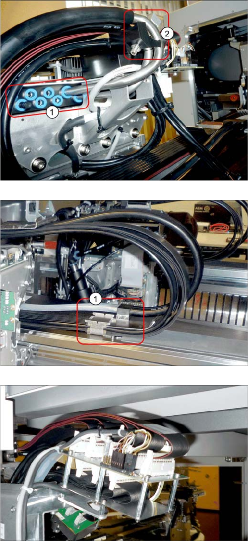
► Use the hose unlocking tool to disconnect all hoses
from the head vacuum distributor (1). You may want
to mark their positions, to make clear assignment
easier later on.
► For vacuum pump operation: Use the hose unlocking
tool to disconnect the vacuum hoses and the retain-
ing bracket (2).
► Disconnect the cable and hose holders (1) from the
gantry.
Gantry interface
► Unplug the connectors for the motor, temperature
sensor and incremental encoder Y axis from the gan-
try interface (see also"4.1 Description of Boards"
[➙69]).
► Unthread the corresponding cable as far as the gan-
try. Open any cable ties on the trailing cable holder.
Mark their positions, to make replacement easier lat-
er on. Pay close attention to the cable ties on the mo-
tor cable.
Installation
Removing the Gantry
60 Gantry Exchange Portaltausch
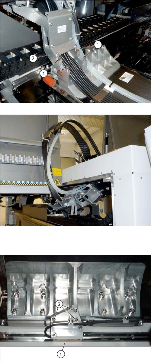
Moving the incremental encoder
► Loosen the screws fastening the trailing cable holder.
Make sure that you do not lose the rubber mat under
the cables.
► Hook the trailing cable (e.g. with cable ties) up, so
that it is not in the way during the remaining removal
tasks.
► Loosen the three screws (2) fastening the Y incre-
mental encoder (1). Move the incremental encoder
as far as possible outwards (away from the scale)
and fix this into place with a screw.
This prevents the incremental encoder or the tape meas-
ure from being damaged during removal.
Installation
Removing the Gantry
Gantry Exchange Portaltausch 61
Removing the gantry
► Hold the gantry well for the following tasks.
If possible, enlist the help of a second person to press the gantry from the outside, towards the center
of the machine. This fixes the gantry into place while it is being screwed down.
► Loosen the last fastening screw. The gantry is now no longer connected to the machine.
► Carefully take the gantry out of the machine. Place it down on a suitable surface, with the side away
from the magnets underneath.
See also
4.1.1 Gantry interface [ ➙ 69]
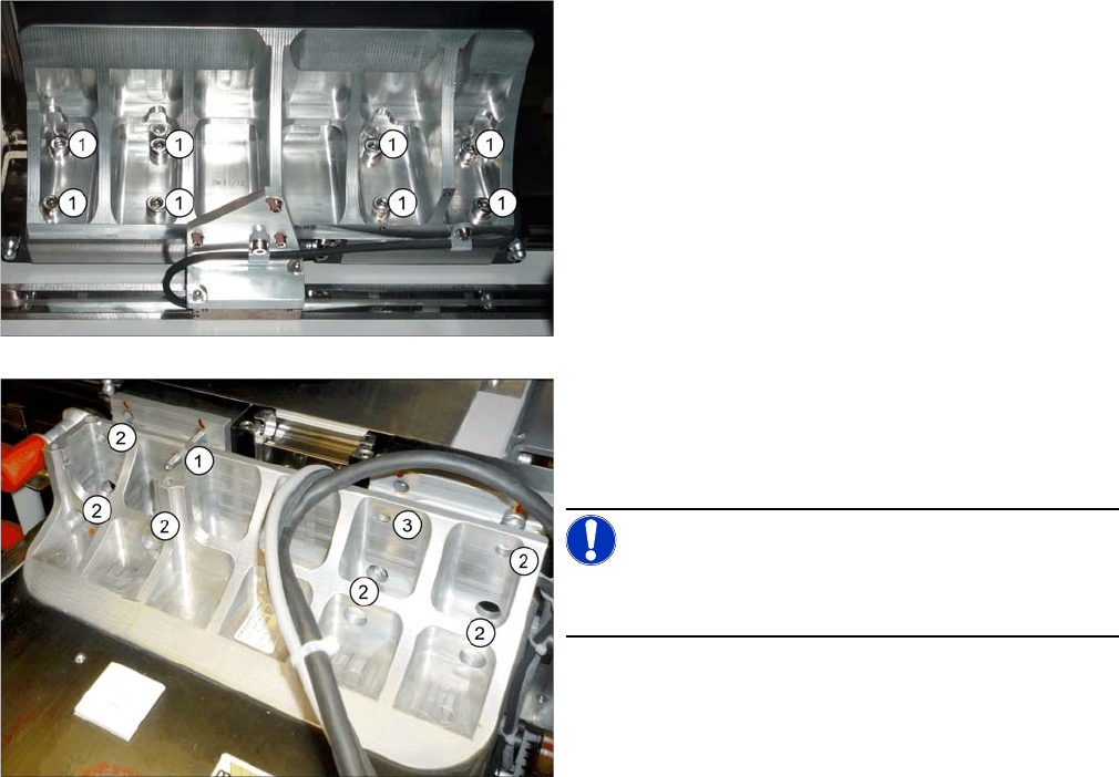
► Make sure that all connections between the gantry
and the machine have been unplugged.
► Loosen the eight screws (1) fastening the underside
of the gantry.
► Replace one of the top fastening screws with a
threaded bolt M6x50 (1). Rotate the threaded bolt
slightly into the thread until the end stop. This gives
the gantry additional support during removal.
NOTICE!
The threaded bolt is used later on to help fit the new gan-
try.
► Loosen the six other fastening screws (2). One fas-
tening screw remains for the moment (3). This is
enough to fix the gantry when it is inactive.