4OM-1505-004_w.pdf - 第92页
4OM-1505 1-41 4. Maintenance Method : Chap.1 4.1.2 Adjustment of Squeegee Head Height Rubber Squeegees Procedure (1) Loosen the set screw for the stopper nut. Stopper Nut L Set Screw Squeegee Head Section F4A34 1002-00…
4OM-1505
1-40
4. Maintenance Method : Chap.1
4. Maintenance Method
4.1 Replacement and Adjustment of Consumables
4.1.1 Replacement of Squeegee
When the squeegee edge is worn out or deformed by solvent, etc., replace the
squeegee with a new one to avoid any hindrance in printing.
•
Loosen the squeegee anchor bolts and detach the squeegee.
•
Attach a new squeegee.
When
the bolt is to be tightened, press the side A of the squeegee against a plain
surface such as a surface plate and tighten the bolt evenly so that there should
be no warpage.
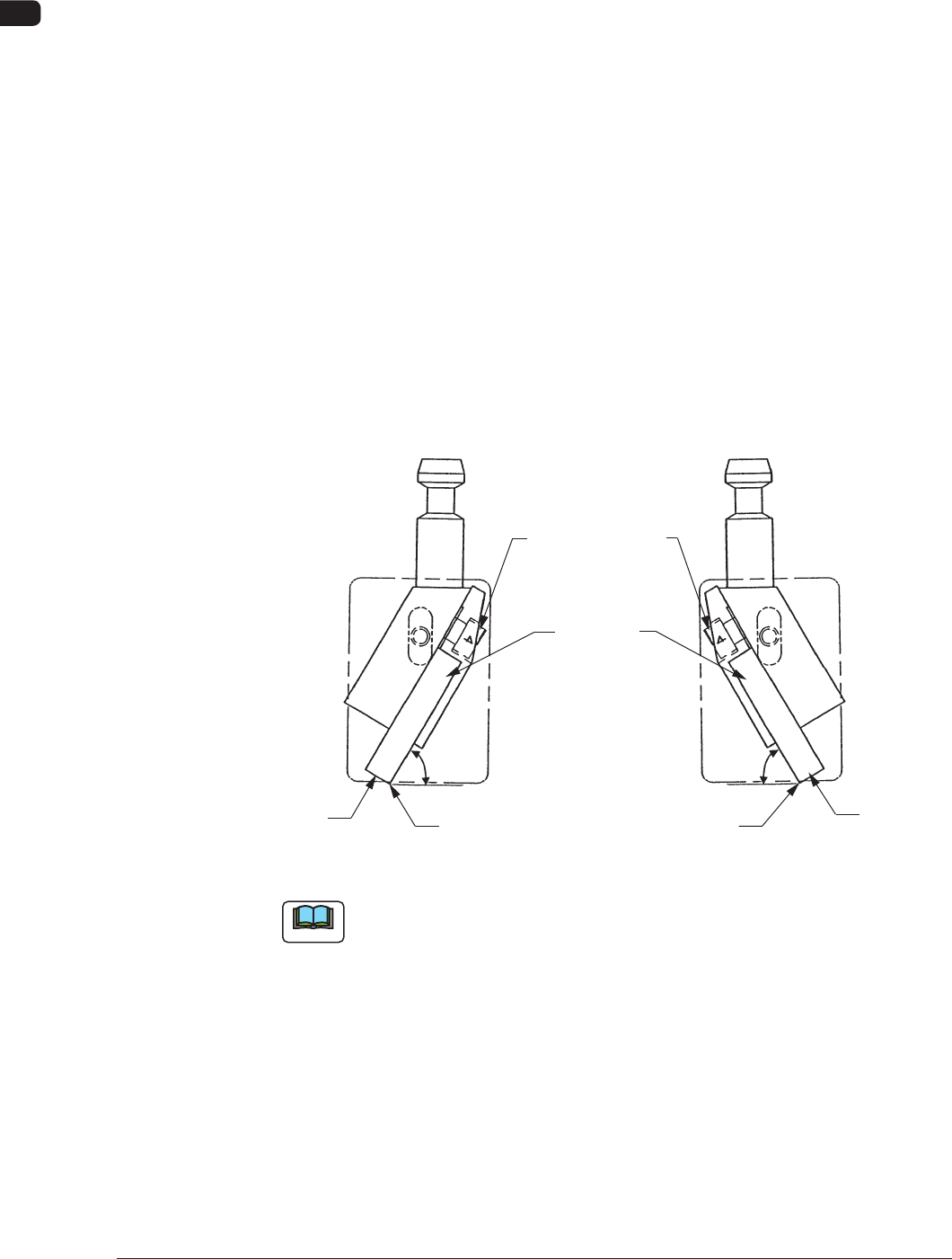
•
After tightening the bolt, push the squeegee against a straight surface such as a
surface plate (edge portion) and conrm that there is no clearance.
Perform the adjustment while the squeegee angle is at 60° (xed) to the surface
plate.
Squeegees Anchor
Bolts
Squeegees
60°
60°
Plane A
Edge Portion
Plane A
Edge Portion
F4A33
Note
It is recommended that Plane A should be ground to secure the straightness with
the squeegee being attached for good printing quality.
Especially, the squeegee with its straightness being well maintained works
effectively for nely-pitched pattern printing and accurate coating (thickness) of
paste.
0906-001
4OM-1505
1-41
4. Maintenance Method : Chap.1
4.1.2 Adjustment of Squeegee Head Height
Rubber Squeegees
Procedure
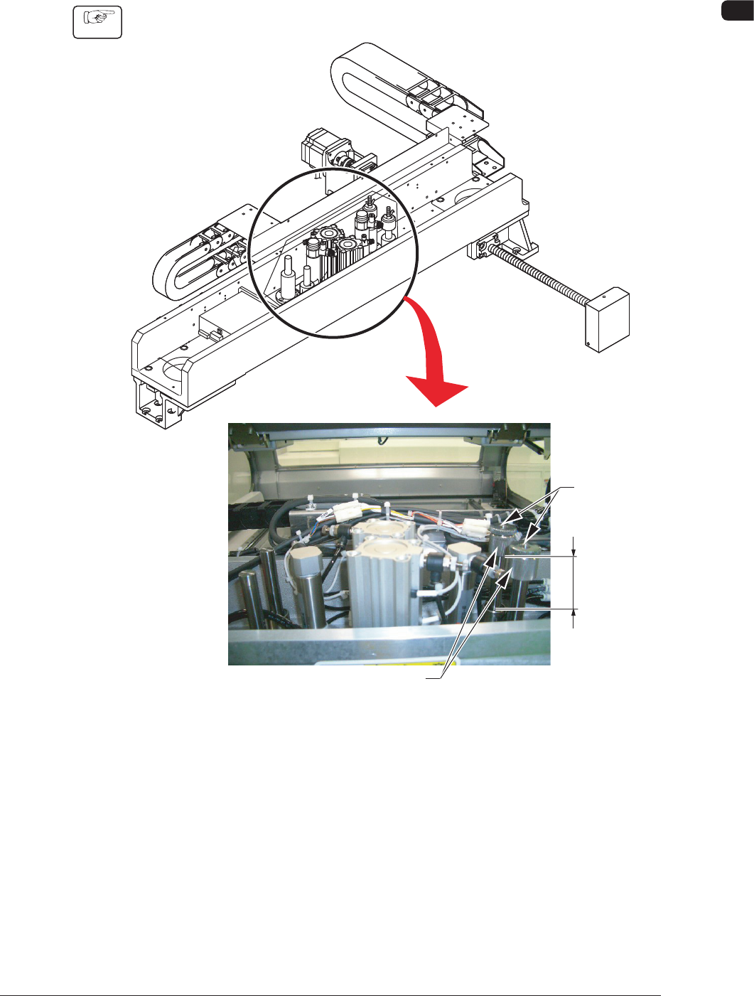
(1) Loosen the set screw for the stopper nut.
Stopper Nut
L
Set Screw
Squeegee Head Section F4A34
1002-002
4OM-1505
1-42
4. Maintenance Method : Chap.1
(2) Adjust the pushing distance by changing Dimension L (the distance between
the upper end plane of the ball bushing and the lower end plane of the
stopper nut).
(3) Use the "Print Block" window to push the squeegees against the PCB located
at the printing position. (Operation Sequence: [MAINT.] Button → [MAN.
SUB-SYS] Button → "Print Block" Tab)
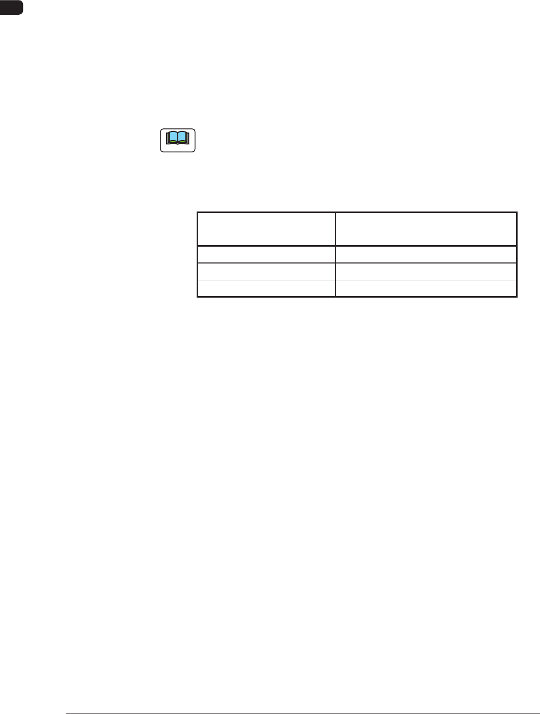
Refer to the T4A12 and check the relation between Dimension L and the
pushing distances.
(4) Fasten the set screw for the stopper nut.
Note
The pushing distance of the squeegee against the stencil is set to "1.0 mm".
(Factory-Adjusted upon Shipment)
When the stopper nut is turned once clockwise, the pushing distance becomes
shorter by 1.0 mm. Turning the stopper nut once counterclockwise makes the
pushing distance longer by 1.0 mm.
Pushing Distances Dimension L during Upward
Movement of Cylinder
0.5 mm 57.0 mm
1.0 mm 57.5 mm (Standard Setting)
1.5 mm 58.0 mm
T4A12
1002-002