00198142-01_AI_Stationary-Camera-25-33_TX_de_en.pdf - 第73页
Installation Fitting the Stationary Camera Type SST25 Stationary Camera Typ e 25/33 Stationäre Kamera Typ 25/33 73 3.3 3 . 3 F it t in g t h e S t a t io n a r y C a m e r a T y p e S S T 2 5 Fitting the Stationary Camer…
Installation
Converting the Reject Box
72 Stationary Camera Type 25/33 Stationäre Kamera Typ 25/33
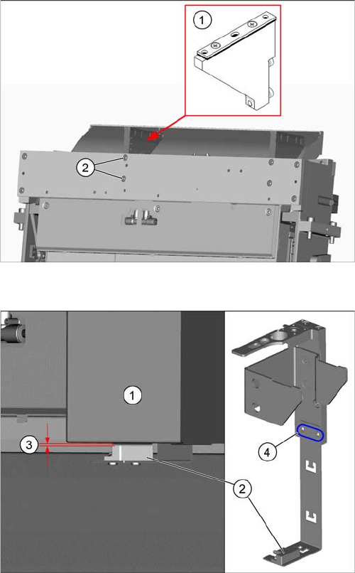
Fitting the NC holder
► Fit the right NC holder (1) with two fastening screws
DIN 7984-M6 x 12-A2-70 [03081847-xx] (2). Replace
the right NC holder by the supplied version without
nozzle station.
Do not fit the NC and the nozzle station yet!
Setting the sensor
1. Reject box
2. Sensor
3. Distance 2.0+/-1.0 mm
4. Fastening screws for setting the senor height
► Insert the reject bin.
► Set the sensor to a distance of 2.0+/-1.0 mm from the
reject bin.
Installation
Fitting the Stationary Camera Type SST25
Stationary Camera Type 25/33 Stationäre Kamera Typ 25/33 73
3.3
3.3 Fitting the Stationary Camera Type SST25
Fitting the Stationary Camera Type SST25
This section describes the installation of a stationary camera of type SST25 GigE.
For installing a stationary camera of type SST33 GigE, refer to section "3.4 Fitting the Stationary Camera
Type SST33" [ ➙ 77].
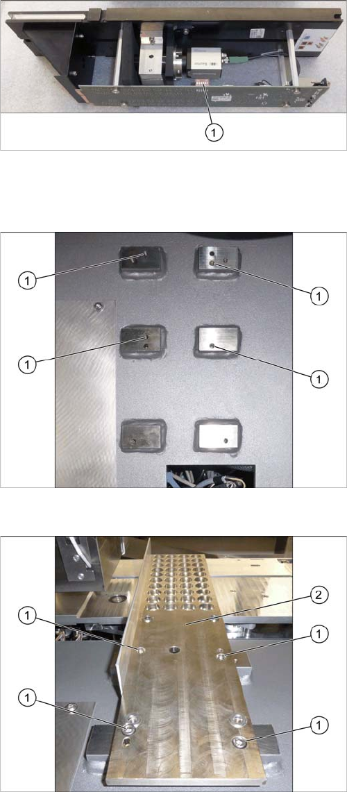
Setting the DIP Switches
Fitting the Support Plate
Setting the DIP Switches
► Set the DIP switches (1):
S1.1 to S1.6: OFF
(See also "4.2.1.1 Vision LED Controller VLC25 GigE
DTC [03117587-xx]" [ ➙ 87]).
Screw points support plate
1. Four screw points on the support plate
Fitting the Support Plate
1. Four fastening screws of the support plate
DIN912-M6x12-A2-70 [03045087
-
xx]
2. Support plate FC [03077911
-
xx]
► Fasten the support plate with four screws.
Installation
Fitting the Stationary Camera Type SST25
74 Stationary Camera Type 25/33 Stationäre Kamera Typ 25/33
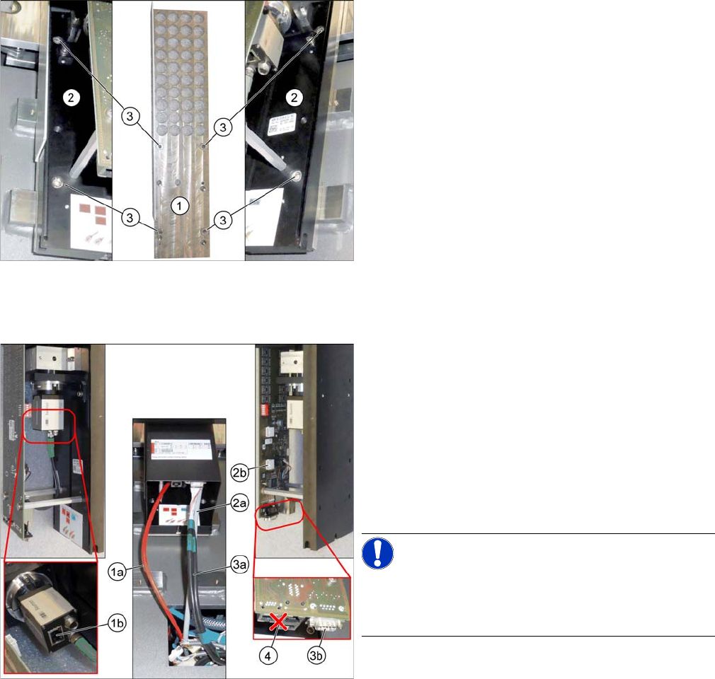
Fitting the Basic Camera Unit
Establishing Electrical Connections
Fitting the Basic Camera Unit
1. Support plate
2. Basic camera unit
3. Four fastening screws of the basic camera unit
ISO4762-M6x20-A2-70 [03042574
-
xx]
► Place the basic camera unit at its installation position
from above.
► Fasten the basic camera unit to the support plate with
four screws.
Establishing Electrical Connections
1. a) GigE cable W122 [03112124
-
xx]
b) Connection for GigE cable
2. a) Power cable W28.1 [03112125
-
xx]
b) Connection for power cable
3. a) CAN bus cable W102 [03112166-xx]
b) Connection for CAN bus cable
4. Multiplexer (not in use)
► Connect the cables.
NOTICE!
Make sure to connect the GigE cable correctly.
The multiplexer connection at the lower end of the board
is not used.