00198142-01_AI_Stationary-Camera-25-33_TX_de_en.pdf - 第75页
Installation Fitting the Stationary Camera Type SST25 Stationary Camera Typ e 25/33 Stationäre Kamera Typ 25/33 75 Hooking in the bottom cover Inserting the Dust Cover Hooking in th e bottom c over ► Hook the bottom cove…
Installation
Fitting the Stationary Camera Type SST25
74 Stationary Camera Type 25/33 Stationäre Kamera Typ 25/33
Fitting the Basic Camera Unit
Establishing Electrical Connections
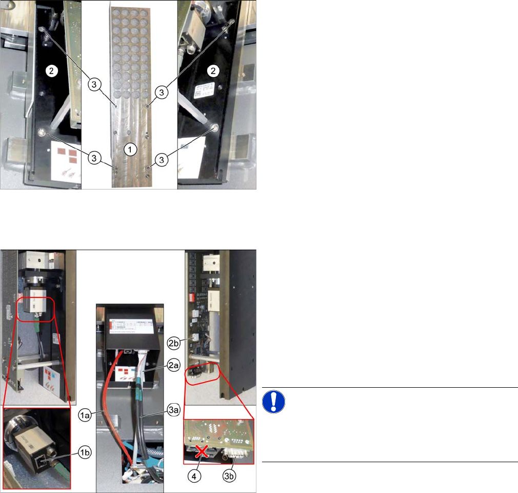
Fitting the Basic Camera Unit
1. Support plate
2. Basic camera unit
3. Four fastening screws of the basic camera unit
ISO4762-M6x20-A2-70 [03042574
-
xx]
► Place the basic camera unit at its installation position
from above.
► Fasten the basic camera unit to the support plate with
four screws.
Establishing Electrical Connections
1. a) GigE cable W122 [03112124
-
xx]
b) Connection for GigE cable
2. a) Power cable W28.1 [03112125
-
xx]
b) Connection for power cable
3. a) CAN bus cable W102 [03112166-xx]
b) Connection for CAN bus cable
4. Multiplexer (not in use)
► Connect the cables.
NOTICE!
Make sure to connect the GigE cable correctly.
The multiplexer connection at the lower end of the board
is not used.
Installation
Fitting the Stationary Camera Type SST25
Stationary Camera Type 25/33 Stationäre Kamera Typ 25/33 75
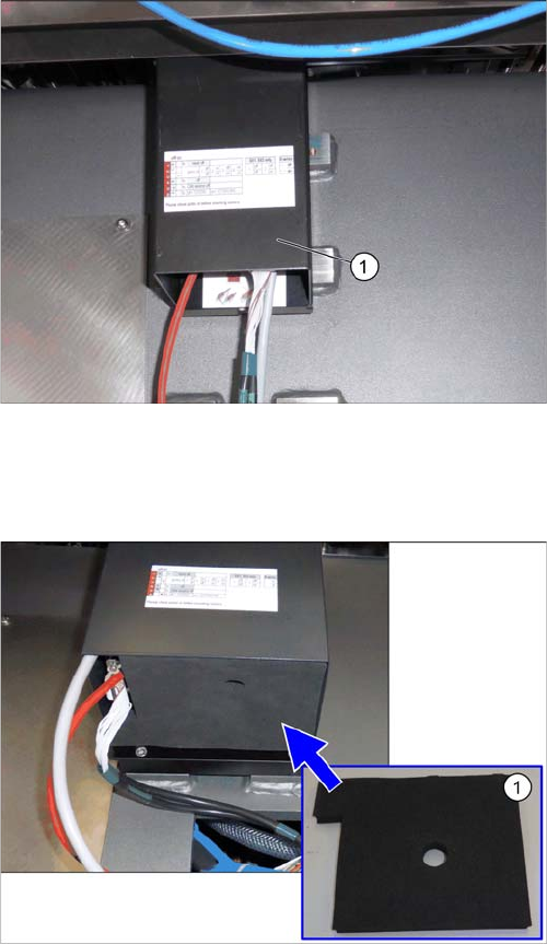
Hooking in the bottom cover
Inserting the Dust Cover
Hooking in the bottom cover
► Hook the bottom cover (1) of the camera in.
Inserting the dust cover (SST33 as example)
► Insert the dust cover made of foam plastic (1) into the
bottom cover.
Installation
Fitting the Stationary Camera Type SST25
76 Stationary Camera Type 25/33 Stationäre Kamera Typ 25/33
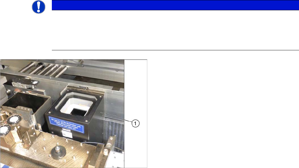
Putting on the Upper Part and Checking the Installation Height
NOTE: The upper section of the camera is assigned specifically to the lower section of the camera!
NOTICE
The upper section of the camera is assigned specifically to the lower section of the camera!
The upper section of the camera may not be used with a different bottom section. Both the up
-
per and lower sections are mechanically and electrically coordinated and may not be ex
-
changed for use with other cameras. The serial and version numbers of the top and bottom
sections of the camera must be identical.
Putting on the Upper Part and Checking the Installation
Height
► Put the upper part (1) on the basic unit.
► Check the installation height. The support plate and
the upper part must be below the top edge of the con
-
veyor rail.