00198142-01_AI_Stationary-Camera-25-33_TX_de_en.pdf - 第82页
Installation Making the Settings in the Software 82 Stationary Camera Type 25/33 Stationäre Kamera Typ 25/ 33 3.6 3 . 6 M a k in g t h e S e t t in g s in t h e S o f t w a r e Making the Settings in the Software SST25: …
Installation
Completing the Mechanical Work
Stationary Camera Type 25/33 Stationäre Kamera Typ 25/33 81
See also
4.2.1.1 Vision LED Controller VLC25 GigE DTC [03117587-xx] [ ➙ 87]
3.5
3.5 Completing the Mechanical Work
Completing the Mechanical Work
► Fasten the COT insert to its original position.
► Check and correct the height of the NC holder (see "4.1.2.1 Setting the Nozzle Changer Height"
[➙84]).
► Check and correct the height of the nozzle changer (see "4.1.2.2 Setting the Height of the Nozzle
Station" [ ➙ 85]).
► Check the setting of the jumper on the NC (if one is present).
It must be set to 2-3 (see also "4.1.2.3 Jumpers on the Nozzle Changer" [ ➙ 86]).
► Fit the NC and the nozzle station.
► Install the used tape chute in location 1.
► Move the component trolley into the machine.
► Switch the machine on.
► Check the function of the reject bin sensor and set the sensor, if required.
► Make the settings in the software (see "3.6 Making the Settings in the Software" [ ➙ 82]).
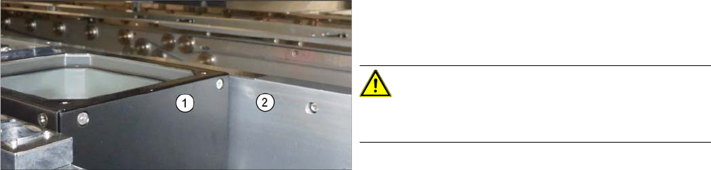
Checking the installation height
► Check the installation height.
When installed correctly, the upper part (1) is 2 mm
higher than the top edge of the conveyor rail (2).
CAUTION!
If the upper part protrudes too far, there is the danger of
a head crash.
Installation
Making the Settings in the Software
82 Stationary Camera Type 25/33 Stationäre Kamera Typ 25/33
3.6
3.6 Making the Settings in the Software
Making the Settings in the Software
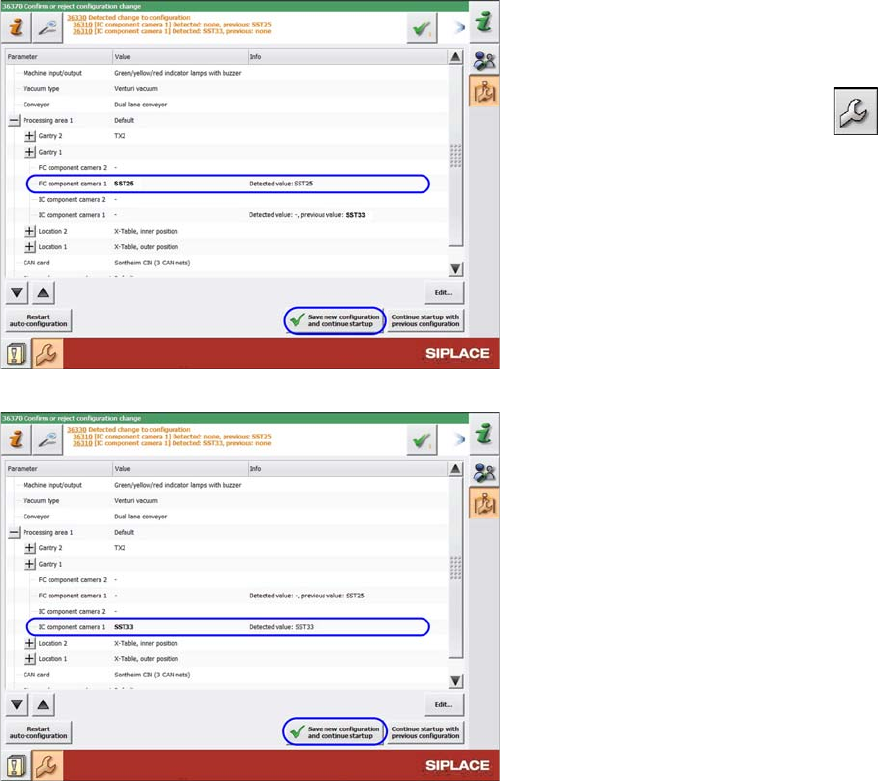
SST25: Saving the configuration
SST33: Saving the configuration
After start-up, the station software notifies you of the
changed hardware. Confirm the change as follows:
► Switch over to the operator level Machine service.
► Switch over to the service menu .
► Go to the Machine Configuration view.
► Check the setting of the PCB camera.
► Confirm the changes with Save new configuration
and continue startup.
► Calibrate the camera (see "4.1.1 Calibrating the
Heads and Cameras (SW70x)" [ ➙ 83]).
The installation is now complete.
Appendix
4.1.1 Calibrating the Heads and Cameras (SW70x) Excerpts from the Service Manual
Stationary Camera Type 25/33 Stationäre Kamera Typ 25/33 83
4
4 Appendix
Appendix
4.1
4.1 Excerpts from the Service Manual
Excerpts from the Service Manual
The following chapters are excerpts from the service manual. For more information, refer to the full ser
-
vice manual for your machine.
4.1.1
4.1.1 Calibrating the Heads and Cameras (SW70x)
Calibrating the Heads and Cameras (SW70x)
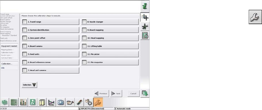
Automatic calibration (SW707)
► Switch over to the operator level Service (Customer).
► Switch over to the Service menu and select Ma
-
chine calibration or Automatic calibration (depending
on SW version).
► Select Head and cameras and click on Next.
► On the next page, select the gantries on which the
heads to be calibrated are located and then click on
Next.
► The next step is to check the calibration conditions
(nozzle, calibration tool etc.). Follow the instructions
provided.
After this step, calibration will begin. All required interme
-
diate steps (head height etc.) will be performed automat
-
ically.