00198142-01_AI_Stationary-Camera-25-33_TX_de_en.pdf - 第80页
Installation Fitting the Stationary Camera Type SST33 80 Stationary Camera Type 25/33 Stationäre Kamera Typ 25/ 33 Inserting the Dust Cover Putting on the Upper Part and Checking the Installation Height NOTE: The uppe r …
Installation
Fitting the Stationary Camera Type SST33
Stationary Camera Type 25/33 Stationäre Kamera Typ 25/33 79
Establishing Electrical Connections
Hooking in the bottom cover
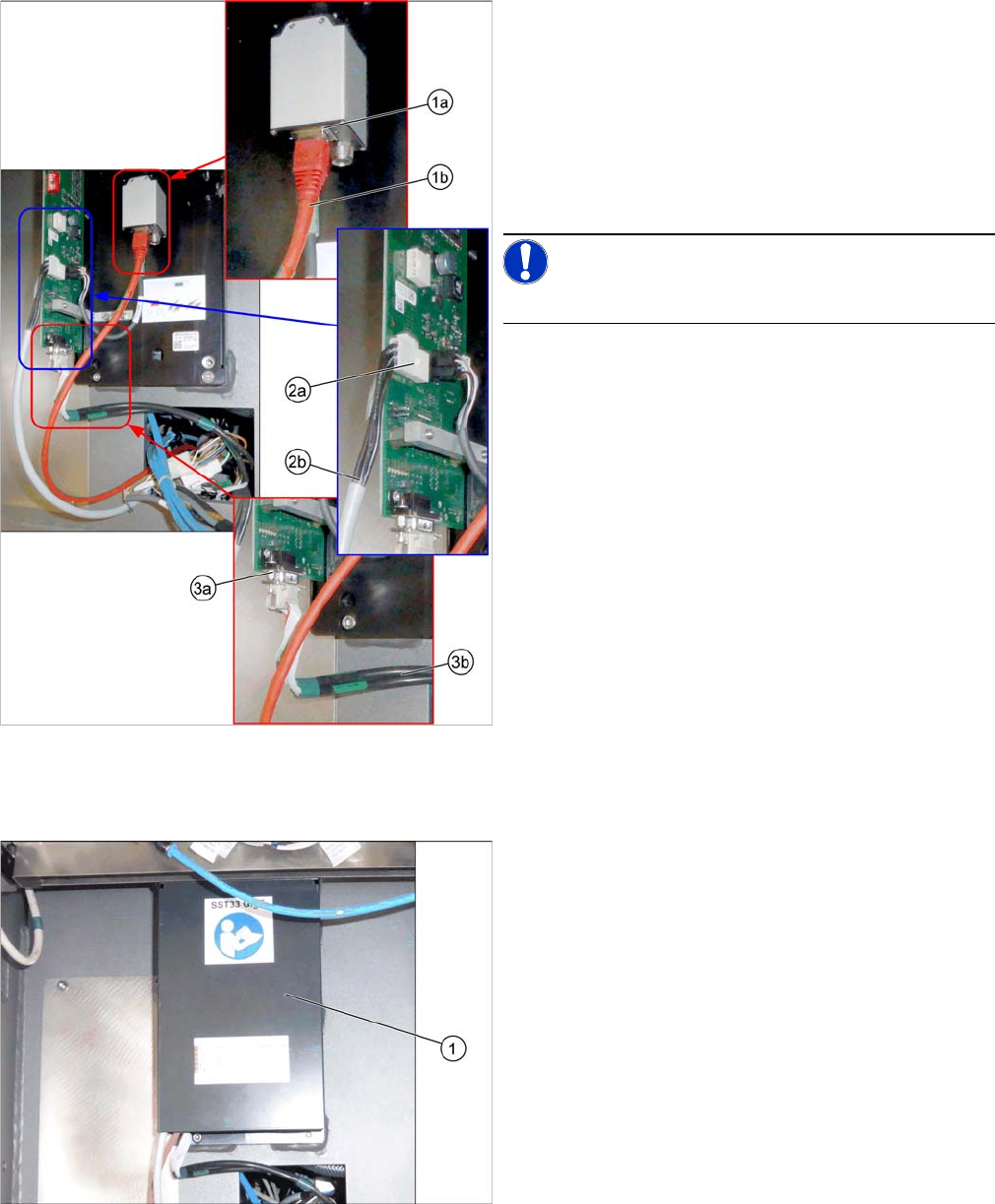
Establishing Electrical Connections
1. a) GigE cable W122 [03112124
-
xx]
b) Connection for GigE cable
2. a) Power cable W28.1 [03112125
-
xx]
b) Connection for power cable
3. a) CAN bus cable W102 [03112166-xx]
b) Connection for CAN bus cable
► Connect the cables.
NOTICE!
Make sure to connect the GigE cable correctly.
Hooking in the bottom cover
► Hook the bottom cover (1) of the camera in.
Installation
Fitting the Stationary Camera Type SST33
80 Stationary Camera Type 25/33 Stationäre Kamera Typ 25/33
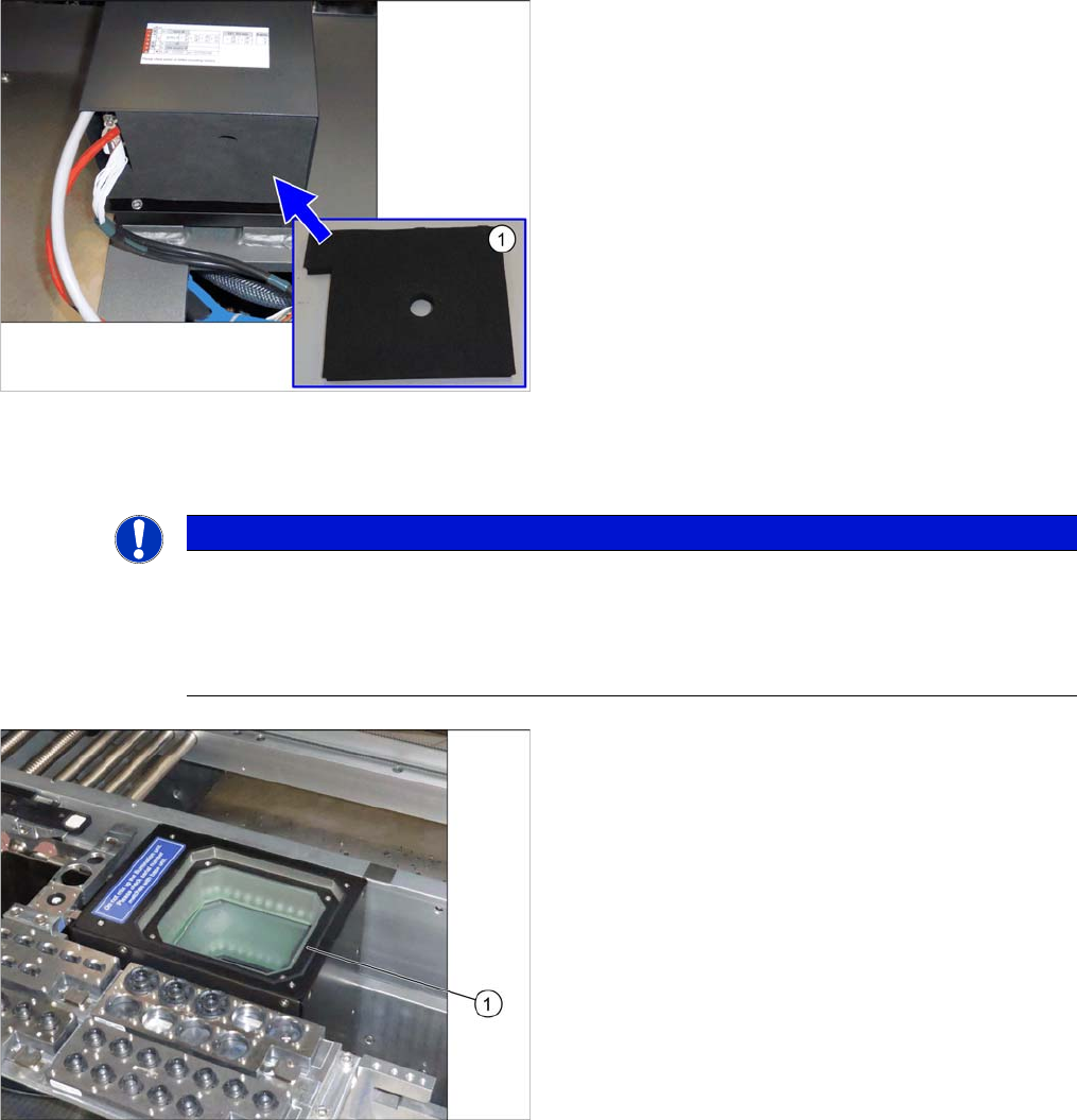
Inserting the Dust Cover
Putting on the Upper Part and Checking the Installation Height
NOTE: The upper section of the camera is assigned specifically to the lower section of the camera!
Inserting the Dust Cover
► Insert the dust cover made of foam plastic (1) into the
bottom cover.
NOTICE
The upper section of the camera is assigned specifically to the lower section of the camera!
The upper section of the camera may not be used with a different bottom section. Both the up
-
per and lower sections are mechanically and electrically coordinated and may not be ex
-
changed for use with other cameras. The serial and version numbers of the top and bottom
sections of the camera must be identical.
Putting on the upper part
► Put the upper part (1) on the basic unit.
Installation
Completing the Mechanical Work
Stationary Camera Type 25/33 Stationäre Kamera Typ 25/33 81
See also
4.2.1.1 Vision LED Controller VLC25 GigE DTC [03117587-xx] [ ➙ 87]
3.5
3.5 Completing the Mechanical Work
Completing the Mechanical Work
► Fasten the COT insert to its original position.
► Check and correct the height of the NC holder (see "4.1.2.1 Setting the Nozzle Changer Height"
[➙84]).
► Check and correct the height of the nozzle changer (see "4.1.2.2 Setting the Height of the Nozzle
Station" [ ➙ 85]).
► Check the setting of the jumper on the NC (if one is present).
It must be set to 2-3 (see also "4.1.2.3 Jumpers on the Nozzle Changer" [ ➙ 86]).
► Fit the NC and the nozzle station.
► Install the used tape chute in location 1.
► Move the component trolley into the machine.
► Switch the machine on.
► Check the function of the reject bin sensor and set the sensor, if required.
► Make the settings in the software (see "3.6 Making the Settings in the Software" [ ➙ 82]).
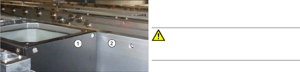
Checking the installation height
► Check the installation height.
When installed correctly, the upper part (1) is 2 mm
higher than the top edge of the conveyor rail (2).
CAUTION!
If the upper part protrudes too far, there is the danger of
a head crash.