PCP-Manual-REV-C.pdf - 第25页
PCP Series Manual Revision B / October 2021 Page 25 of 56 Figure 24 : Fluid Block Installe d 6. Install the two M3 x 35 mm socket head cap screws onto t he rotor assembly and fluid block. Tighten with a 2.5 mm hex key. F…
PCP Series Manual
Revision B / October 2021
Page 24 of 56
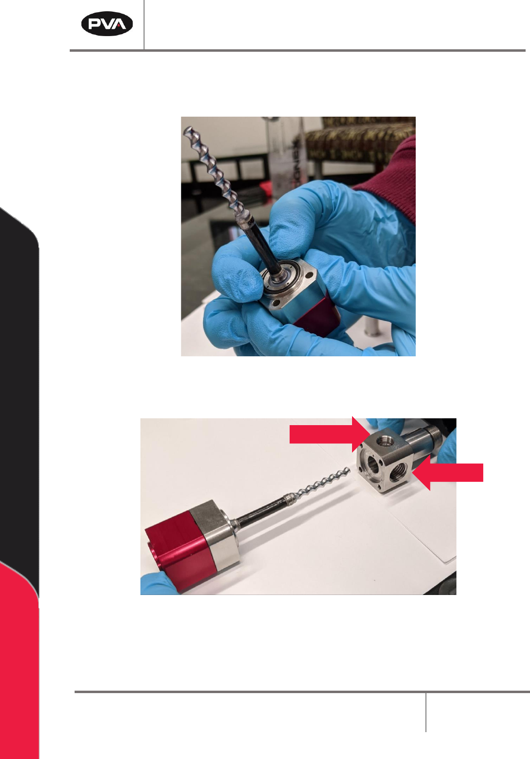
3. Lubricate the AN016 O-ring with pump conditioner.
4. Install the AN016 O-ring onto the seal block.
Figure 22: Install O-Ring on Seal Block
5. Install the fluid block onto the seal block/rotor assembly.
Figure 23: Install Fluid Block
Note: When installing the fluid block, ensure that the bleed port is on the front and
the fluid inlet is on the outer side of the pump. For example, in the left pump pictured
above, the fluid inlet is on the left side.
Bleed Port
Fluid Inlet
PCP Series Manual
Revision B / October 2021
Page 25 of 56
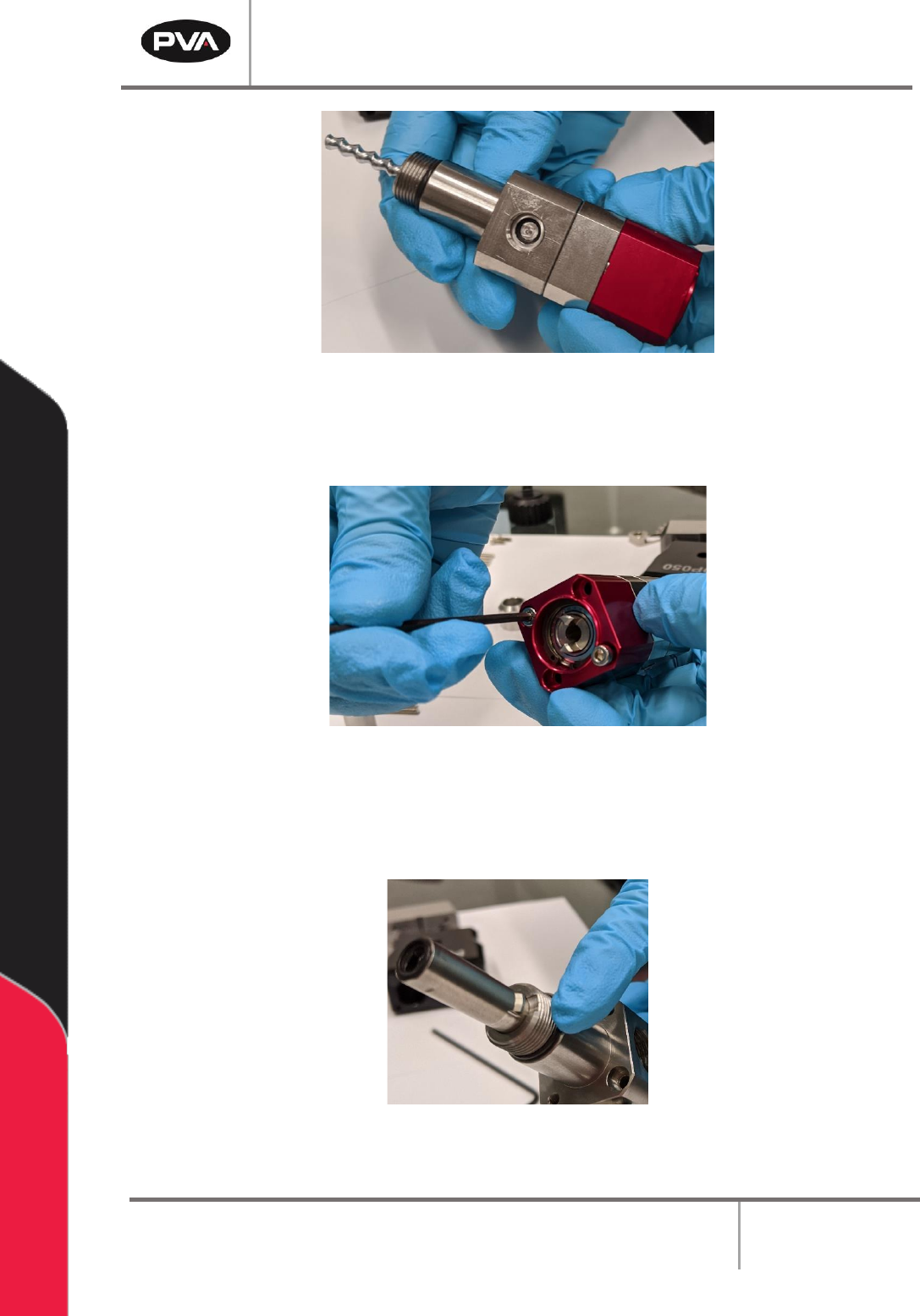
Figure 24: Fluid Block Installed
6. Install the two M3 x 35 mm socket head cap screws onto the rotor assembly and
fluid block. Tighten with a 2.5 mm hex key.
Figure 25: Install Screws onto Rotor Assembly/Fluid Block
7. Lubricate the AS013 O-ring with pump conditioner.
8. Install the o-ring on the bottom of the fluid block assembly.
Figure 26: Install O-Ring on Fluid Block Assembly
PCP Series Manual
Revision B / October 2021
Page 26 of 56
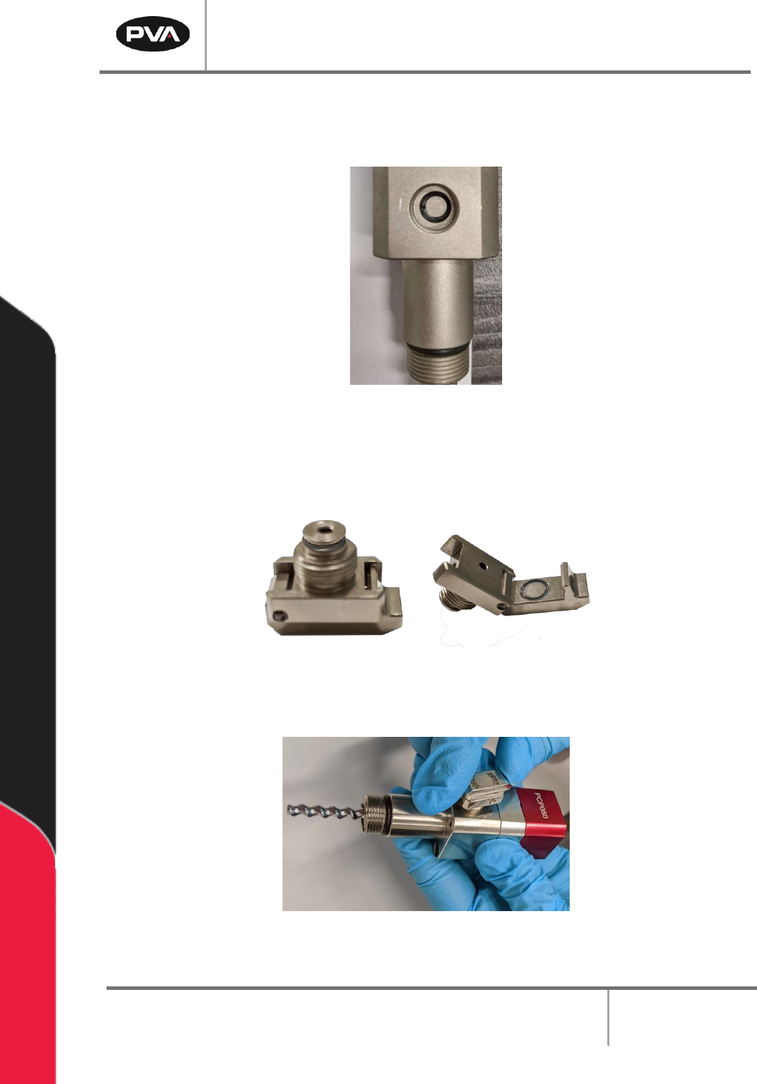
9. Lubricate the SS5 O-ring with pump conditioner.
10. Install the SS5 O-ring onto the vent port.
Figure 27: Install O-Ring on Vent Port
11. Lubricate the SS5 O-rings with pump conditioner.
12. Install the SS5 O-rings on the bleed clip based on the picture below.
Figure 28: Install O-Rings on Bleed Clip
13. Install the bleed clip onto the vent port.
Figure 29: Install Bleed Clip