PCP-Manual-REV-C.pdf - 第26页
PCP Series Manual Revision B / October 2021 Page 26 of 56 9. Lubricate the SS5 O-ring with pump condition er. 10. Install the SS5 O-ring onto the vent port. Figure 27 : Install O-Ring on Vent Port 11. Lubricate the SS5 O…
PCP Series Manual
Revision B / October 2021
Page 25 of 56
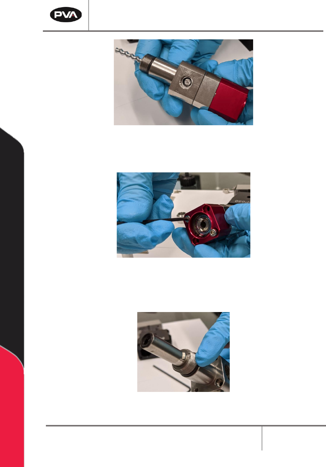
Figure 24: Fluid Block Installed
6. Install the two M3 x 35 mm socket head cap screws onto the rotor assembly and
fluid block. Tighten with a 2.5 mm hex key.
Figure 25: Install Screws onto Rotor Assembly/Fluid Block
7. Lubricate the AS013 O-ring with pump conditioner.
8. Install the o-ring on the bottom of the fluid block assembly.
Figure 26: Install O-Ring on Fluid Block Assembly
PCP Series Manual
Revision B / October 2021
Page 26 of 56
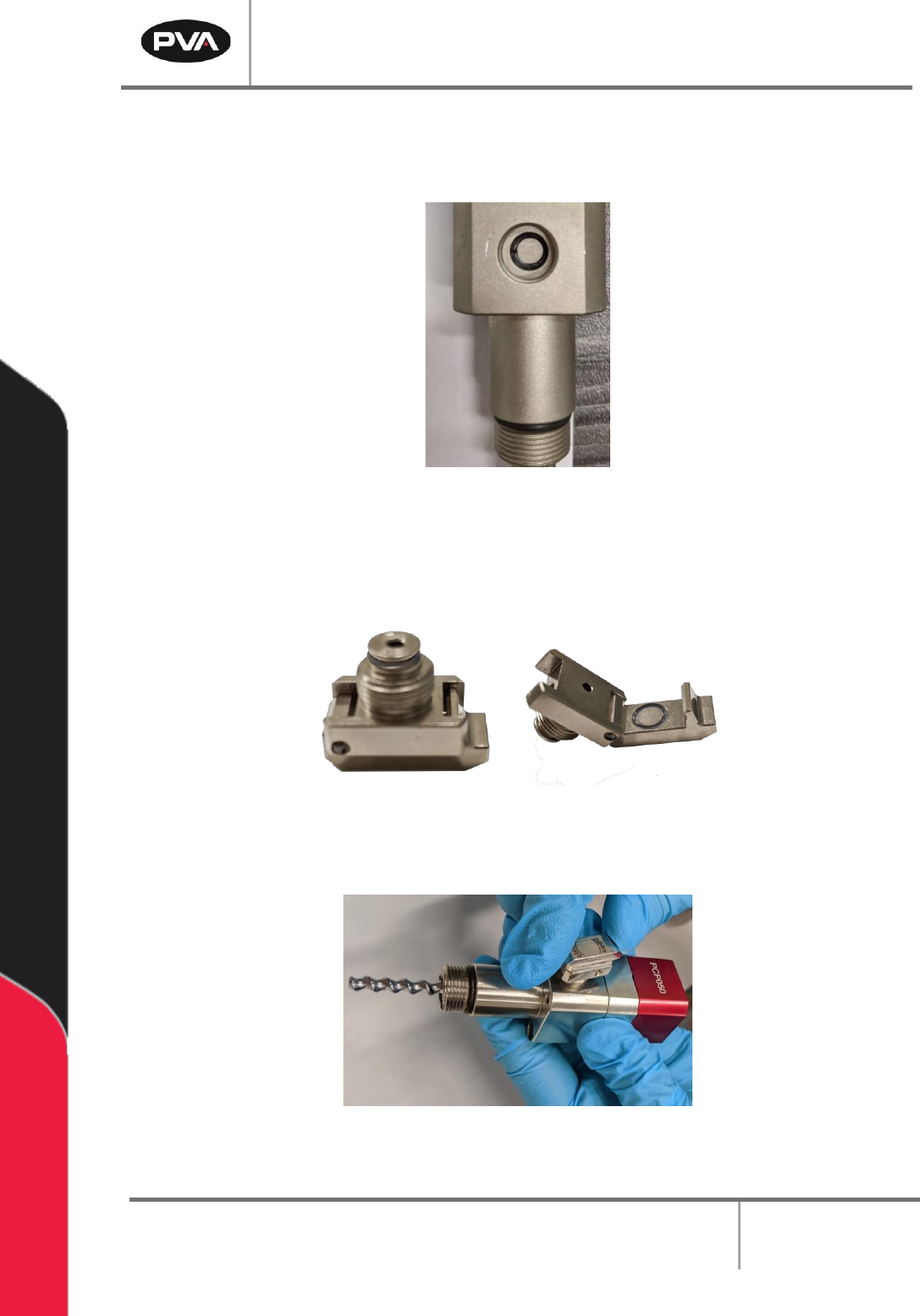
9. Lubricate the SS5 O-ring with pump conditioner.
10. Install the SS5 O-ring onto the vent port.
Figure 27: Install O-Ring on Vent Port
11. Lubricate the SS5 O-rings with pump conditioner.
12. Install the SS5 O-rings on the bleed clip based on the picture below.
Figure 28: Install O-Rings on Bleed Clip
13. Install the bleed clip onto the vent port.
Figure 29: Install Bleed Clip
PCP Series Manual
Revision B / October 2021
Page 27 of 56
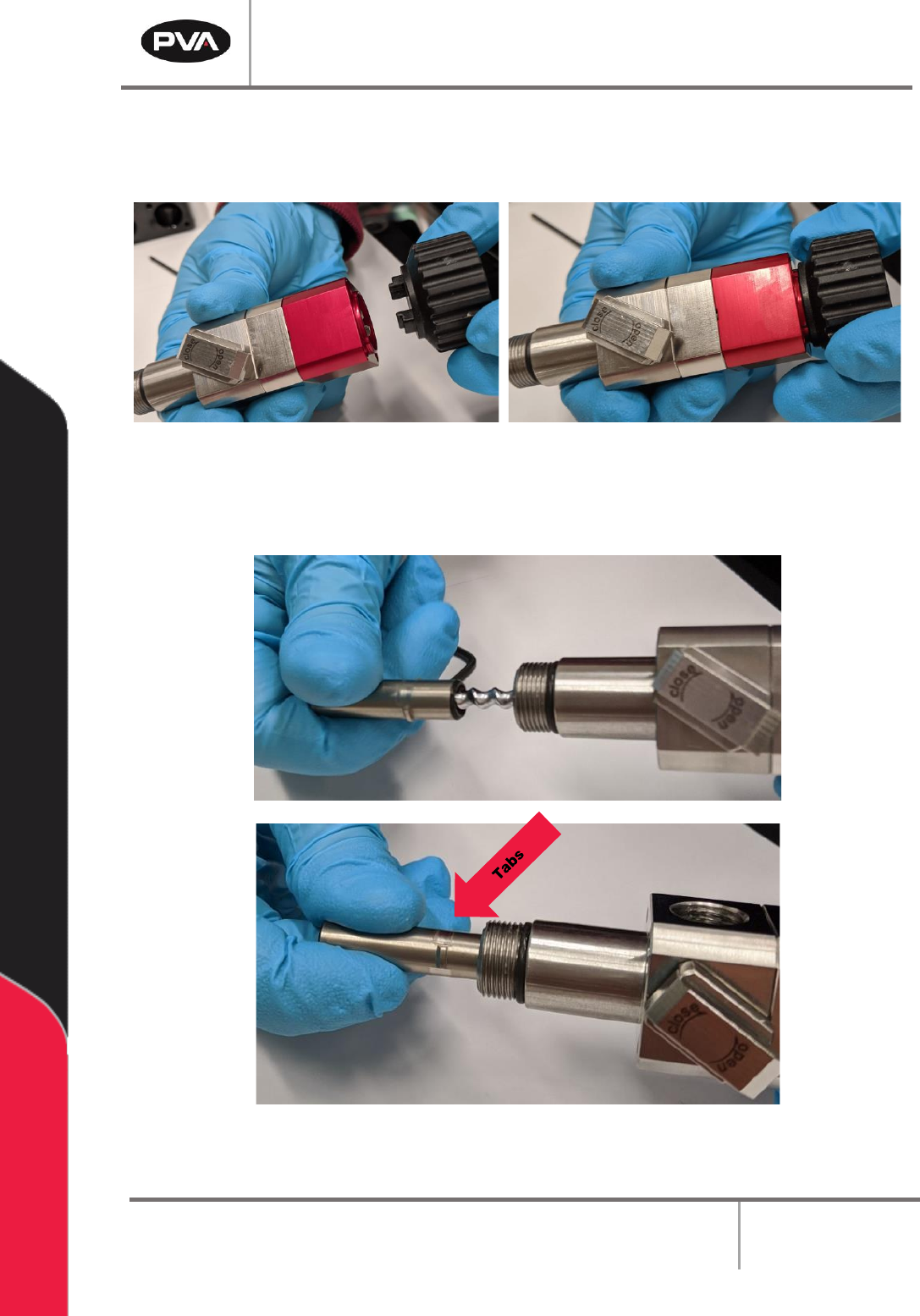
14. Apply pump conditioner to the rotor.
15. Install the stator tool onto the rotor assembly.
Figure 30: Install Stator Tool
16. Face the tabs of the stator toward the fluid block assembly. Hold the stator tool to
stabilize and twist on the stator.
Figure 31: Install Stator onto Rotor Assembly