OM-1754-001w_GS-F600.pdf - 第189页
5OM-1754 5-31 1303-001-(1015WB---1016) G5S FULL TRA Y T raverse Logic Circuit G5S FULL TRA Y Elevator Logic Circuit 1 2 3 4 5 6 7 8 A B C D E F LPL T OUT R1 RL LPL T OUT F RL (EV1 INTLK) LPL T OUT RS LPL T OUT L T I O LP…
OM-1754
5-301303-001-(1015WB---1015)
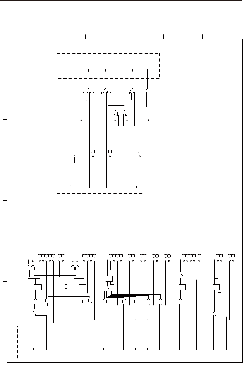
G5S FULL TRAY Traverse Logic Circuit
G5S FULL TRAY Traverse Logic Circuit
1 2 3 4 5 6 7 8
A
B
C
D
E
F
QS
R
TV CHUK O/C RS
O
I
TV CHUK O/C LT
TV CHUK O/C1 RL
TV CK MS A RL
TV CK MS LT
I
I
TV CK MS A RL
(TV CK MS LT)
I
TV CK MS C RL
TV CK MS B RL
I
TV CK MS B RL
O
TV CHUK O/C ED
TV CK MS A ED
O
TV CK MS B ED
O
TV CK MS C ED
O
PLT OUT R RL
PLT OUT R RS
PLT OUT R LT
I
I
O
PLT OUT R RL
O
PLT OUT R ED
TV CK MS C RL
Q
S
R
TV CHUK O/C2 RL
PLT IL SEL EV2
O
O
PLT IL SEL EV1
(PLT IL2 EV1)
(PLT IL2 EV2)
(PLT IL1 EV2)
(PLT IL1 EV1)
EV LOCK L RL
EV LOCK R RL
EV LOCK RS
EV LOCK LT
O
I
QS
R
(EV LOCK LT)
FB CK MS RL
FB CK MS LT
I
FB CK MS ED
R
S Q
(FB IL)
FB FK RL
FB CK MS RS
O
FB CK MS RL
FB FK RL
I
TV CK MS E RL
TV CK MS E ED
O
TV CK MS D RL
TV CK MS RS
O
R
S
EV1 EMG STP
EV2 EMG STP
TV EMG STP
(TV CK MS LT)
(PLT IL1 EV1)
(PLT IL1 EV2)
(PLT IL2 EV2)
(PLT IL2 EV1)
EV1 STP SG RL
EV2 STP SG RL
(EV LOCK LT)
(FB IL)
FB ILK
SF CVR LK RL
I
SF CVR LK RL
I
EV1 STP SG RL
TV CK MS E RL
I
TV CK MS D RL
TV CK MS D ED
O
(CN40)
(CN41)
(CN30)
(CN31)
(CN32)
(CN33)
(CN34)
(CN35)
(CN36)
(CN37)
(CN44)
(CN45)
(CN38)
(CN39)
(CN42)
(CN13)
(CN14)
(CN12)
(CN11)
(di_1-1)
(di_0-12)
(di_1-3)
(do_1-12)
(do_1-13)
(di_0-10)
(di_0-11)
(di_1-0)
(do_1-2)
(do_1-3)
(do_1-0)
(do_1-1)
(do_1-4)
(do_1-5)
(di_0-2)
(di_1-2)
(do_1-6)
(do_1-7)
(di_0-3)
(do_1-8)
(di_0-4)
(do_1-9)
(di_0-5)
(do_1-10)
(di_0-6)
(do_1-11)
(di_0-7)
(do_0-6)
(di_1-5)
(di_0-8)
(do_0-3)
(do_0-4)
(do_0-2)
(do_0-1)
I
TV CHUK O/C1 RL
(di_0-0)
I
TV CHUK O/C2 RL
(di_0-1)
I
EV LOCK L RL
(di_0-14)
I
EV LOCK R RL
(di_0-15)
I
EV2 STP SG RL
(di_0-9)
I
O
I
Q
EMR RL
(CN43)
EMR RL
I
(di_0-13)
The pick-up error sensor latch ED is as follows.
(TV CK MS A ED | TV CK MS B ED | TV CK MS C ED | TV CK MS D ED | TV CK MS E ED)
Insert the noise cancellation circuit in the input section.
Input Delay Time : 300µs to 450µs
Emergency Stop Detection
Feeder Disangaged
Latch Detection
Elevator Unit Clamp
Approach Detection L
Elevator Unit Clamp
Approach Detection R
External Output
External Output
Tray Interlock Detection R
Tray Interlock Detection L
Ejected Pallet Detection
Pick-up Error Component
Detection Down A (12mm)
Tray Pick-up Error Component
Detection Down B (20mm)
Tray Pick-up Error Component
Detection Down C (24mm)
Tray Pick-up Error Component
Detection Down D (30mm)
Tray Pick-up Error Component
Detection Down E (35mm)
FFeeder Pick-up Error Component
Detection Down
EV1(Rower) Interlock Signal
EV2(Upper) Interlock Signal
Traverse Main Power OFF Detection
External Output
EV1(Rower)Motor
Stop Detection
EV1(Upper)Motor
Stop Detection
TV Motor
Stop Detection
Feeder Base
Interlock
5OM-1754
5-311303-001-(1015WB---1016)
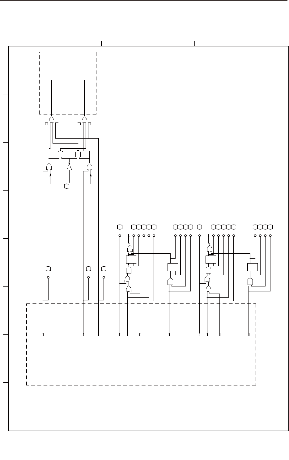
G5S FULL TRAY Traverse Logic Circuit
G5S FULL TRAY Elevator Logic Circuit
1 2 3 4 5 6 7 8
A
B
C
D
E
F
LPLT OUT R1 RL
LPLT OUT F RL
(EV1 INTLK)
LPLT OUT RS
LPLT OUT LT
I
O
LPLT OUT R2 RL
O
LPLT OUT ED
LMGN_POS RL
I
LPLT OUT F RL
UPLT OUT F RL
I
UMGN_POS RL
UPLT OUT R ED
O
UPLT OUT R2 RL
O
I
UPLT OUT R LT
UPLT OUT R RS
UPLT OUT F RL
UPLT OUT R1 RL
S Q
R
R
QS
(EV2 INTLK)
EV1 STP SG
UMGN_POS LT
I
O
I
UMGN_POS RS
UMGN_POS RL
QS
R
UMGN_POS ED
O
R
S Q
LMGN_POS RL
LMGN_POS RS
I
O
I
LMGN_POS LT
O
LMGN_POS ED
EV2 STP SG
CNG STP
O
(EV1 INTLK)
HIGH CVR RL
MID CVR RL
LOW CVR RL
(CN42)
(CN43)
(CN44)
(CN30)
(CN31)
(CN32)
(CN35)
(CN36)
(CN37)
(CN38)
(CN41)
(CN12)
(CN13)
(di_0-0)
(di_1-0)
(do_0-7)
(do_0-8)
(di_1-1)
(do_0-9)
(do_0-10)
(di_0-5)
(di_0-6)
(di_1-2)
(do_0-11)
(do_0-12)
(di_1-3)
(do_0-13)
(do_0-14)
(di_0-11)
(do_0-15)
(U152)
(U152)
(do_0-10)
UPLT OUT R1 RL
I
UPLT OUT R2 RL
I
(di_0-7)
(di_0-8)
LPLT OUT R1 RL
I
LPLT OUT R2 RL
I
(di_0-1)
(di_0-2)
I
LOW CVR RL
(di_0-12)
I
HIGH CVR RL
(di_0-13)
I
MID CVR RL
(di_0-14)
(do_0-11)
(EV2 INTLK)
Stop Axis Change
Insert the noise cancellation circuit in the input section.
Input Delay Time : 300µs to 450µs
Operator Side Rack Shuttar
Close
Detection R
Rower Magazine
External Output
External Output
Safety Door Lock (Upper)
Check
Safety Door Lock (Middle)
Check
Safety Door Lock (Lower)
Check
Operator Side Rack Shuttar
Open/Close
Detection
Rower Magazine
Operator Side Rack Shuttar
Close
Detection L
Rower Magazine
Operator Side Rack Shuttar
Close
Detection R
Upper Magazine
Operator Side Rack Shuttar
Open/Close
Detection
Upper Magazine
Operator Side Rack Shuttar
Close
Detection L
Upper Magazine
Rower Magazine
Positioning Check
Upper Magazine
Positioning Check
EV1 (Rower) Interlock Signal
EV2 (Upper) Interlock Signal

YAMAHA SMT Assembly System
127 Toyooka, Kita-ku, Hamamatsu, Shizuoka 433-8103, Japan
YAMAHA MOTOR CO., LTD Robotics Operations
Telephone 81-53-525-7061 Facsimile 81-53-525-8351
All rights reserved. No part of this publication may be reproduced in any form without the permission
of YAMAHA MOTOR CO., LTD. Information furnished by YAMAHA in this manual is believed to be reliable.
However, no responsibility is assumed for possible inaccuracies or omissions.
If you find any part unclear in this manual, please contact YAMAHA or YAMAHA sales representatives.
OM-1754-001
Instruction Manual March 2013