OM-1754-001w_GS-F600.pdf - 第85页
OM-1754 2-23 2.4.4.2 Editing of T ray Step Information [1] [2] [3] [4] "Tray Step Information [1-15 Step]" window FB21 [1] Block Shown are the block Nos. [2] Fdr .No. Displayed are the Nos. of the feeders arran…
OM-1754
2-22
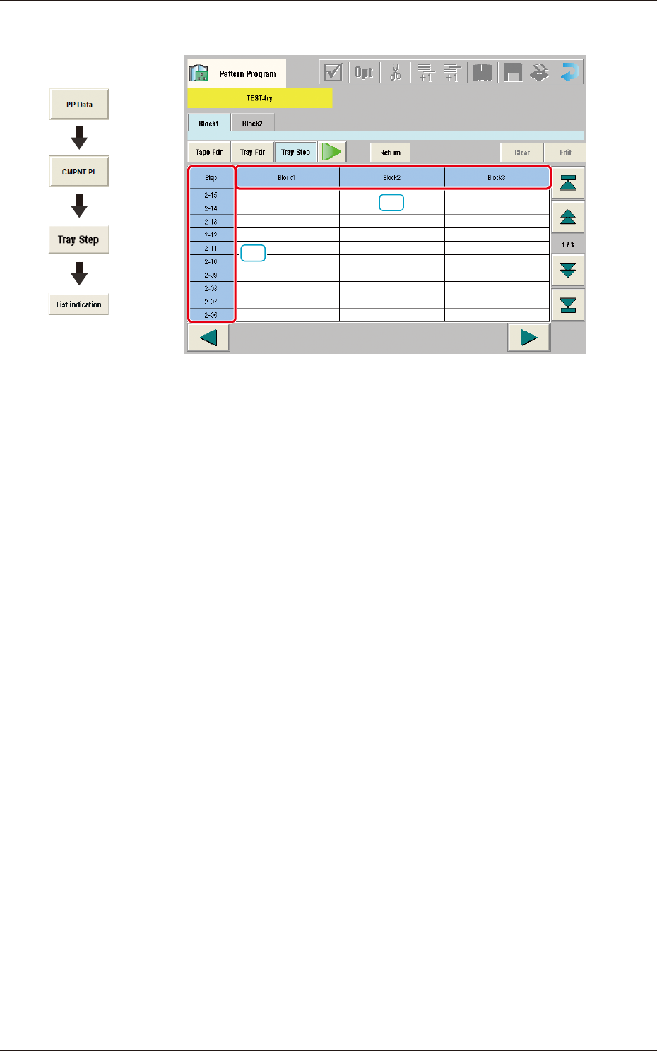
2.4.4.1 "List indication" Window
[1]
[2]
FB20
[1] Step
Shown are the step Nos. of the magazine.
The step Nos. have a button function. When one of these buttons is pressed,
the corresponding "Tray Step Information" window opens.
[2] Block 1 to 9
Specify where in each step and block various components specied in the
tray data should be arranged.
Graphic
Development
1303-001
2.4 "Prod.Dt" Submenu
OM-1754
2-23
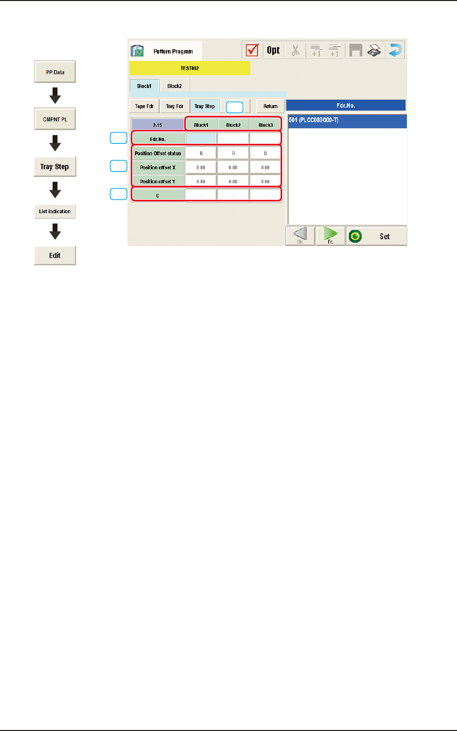
2.4.4.2 Editing of Tray Step Information
[1]
[2]
[3]
[4]
"Tray Step Information [1-15 Step]" window FB21
[1] Block
Shown are the block Nos.
[2] Fdr.No.
Displayed are the Nos. of the feeders arranged in each block.
[3] Position Offset status
Select "R", "L", or "Free Position" as Reference Point X for the block.
Position offset X [mm], Y [mm]
Enter the reference coordinates of the tray viewed from the pallet reference
position of each block.
[4] C
The control commands can be selected.
Graphic
Development
1303-001
2.4 "Prod.Dt" Submenu
OM-1754
2-24
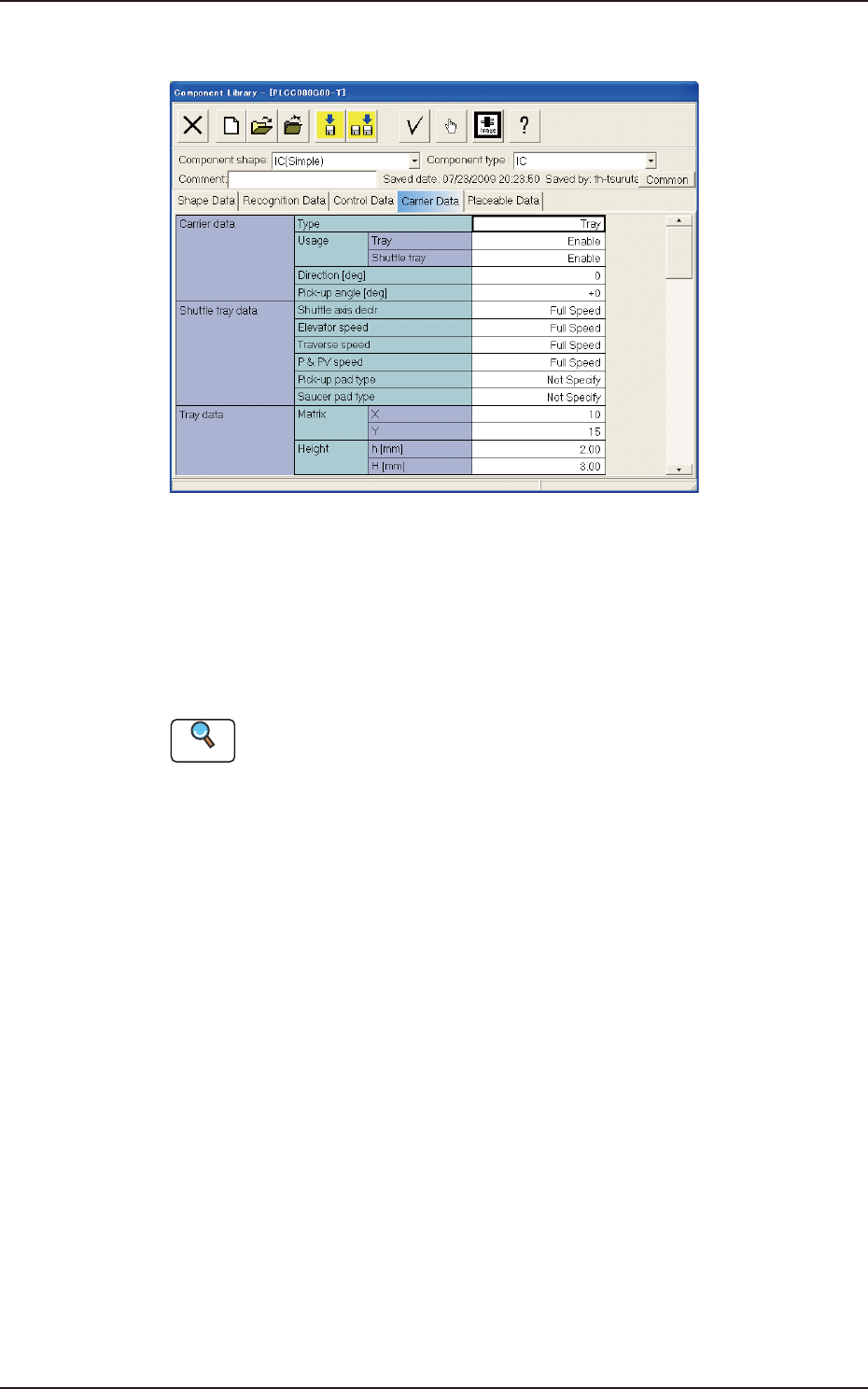
2.4.5 "Component Library" Window
"Carrier Data" Tab sheet FB22
Carrier Data
This is a tab sheet which corresponds to all component shapes - "Cylindrical",
"Square", "Deform", "IC (Simple)", "IC (Complex)", "Connector (Simple)",
"Connector (Complex)", "Other Leaded (Simple)", "Other Leaded (Complex)",
and "BGA/CSP".
Reference
Refer to "1.5 Carrier Data" in "Chapter 2" of the instruction manual "Volume 6 :
Component Library" for details of each data.
Set "Tray" in the "Type" text box of the label "Carrier data" and enter parameters
in the other text boxes of the label "Carrier data" and in the text boxes of the label
"Tray data".
1303-001
2.4 "Prod.Dt" Submenu