OM-1754-001w_GS-F600.pdf - 第89页
OM-1754 2-27 1303-001 3. Product Change Menu 3.1 Outline of Product Change Menu The following shows the hierarchical structure of the menus (including the submenus and windows) for the Product Change Menu. Note The shado…
OM-1754
2-26
[1]
[2]
[3]
[4]
[4]
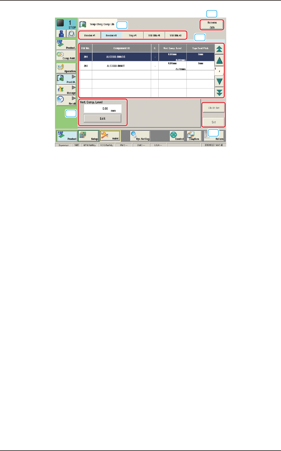
"Comp Crg Dt Edit" window (3/3) FB25
[1] Unit Selection Buttons
These buttons can be used to specify the feeder base whose carrier data
should be conrmed or changed.
[2] Information Display
Displayed is the component carriage data of the feeder base (the multilayer
tray feeder) selected in [1].
[3] Mode Buttons
These buttons are used to change the direction of component feed, the auto
feeder axis adjustment X and Y, the pickup level, and the placement level.
[4] [Screens], [Lib Dt Set], and [Set] Buttons
[Screens] Button
: This button can be used to open another page.
[Lid Dt Set] Button
: When pressed, this button resets the selected
component data to the defaults registered in the
component library.
[Set] Button
: When pressed, this button sets the changed
contents.
1303-001
2.4 "Prod.Dt" Submenu
OM-1754
2-271303-001
3. Product Change Menu
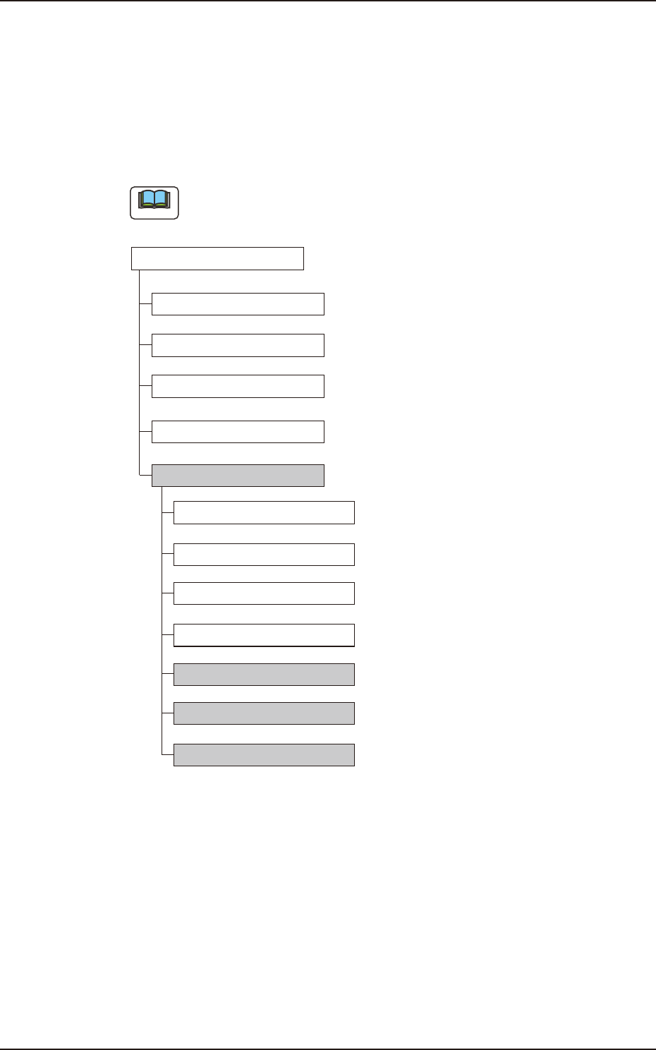
3.1 Outline of Product Change Menu
The following shows the hierarchical structure of the menus (including the
submenus and windows) for the Product Change Menu.
Note
The shadowed (gray) items are related to the multi-layer tray feeder.
"Setup" Window
"PP CHANGE" Window
"SPRT-PINS" Window
"PCB XFER" Window
"NOZ.CHG." Window
"Fdr Pick-up Tch" Window
"XY Beam Test" Window
"COMP RCG" Window
"PEC RCG" Window
"Tray Matrix Tch" Window
"Tray PU Pos Tch" Window
"PU Pos Ofst Tch" Window
"Test & Tch" Submenu
3.2.3
3.2.1
3.2
3.2.2
Reference Item Nos
Outline of Product Change Menu FB26
3. Product Change Menu
OM-1754
2-28
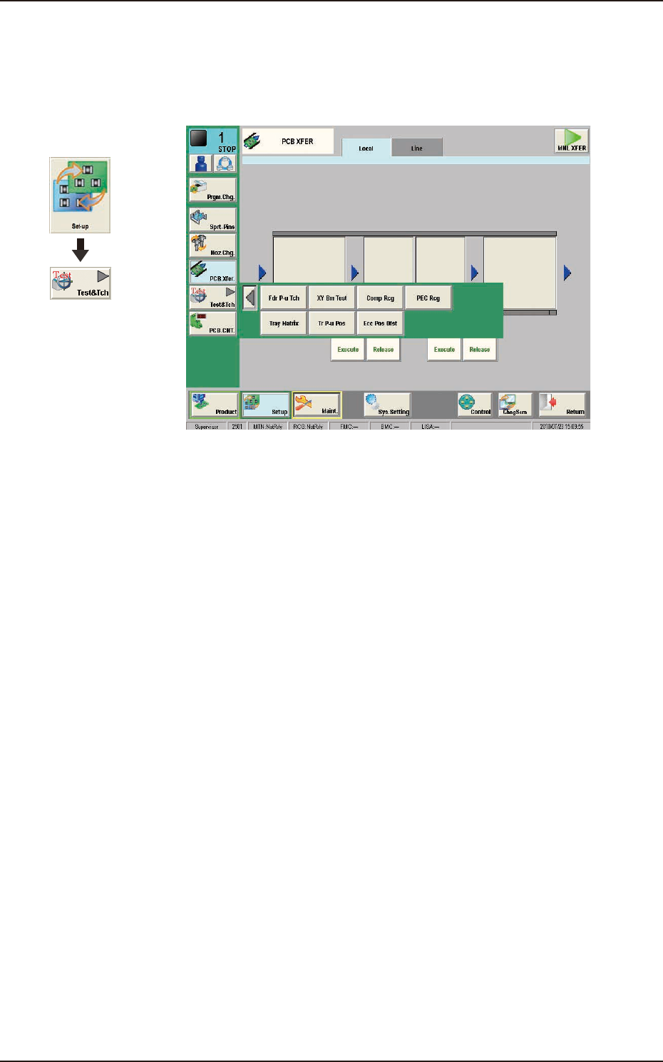
3.2 "Test & Tch" Submenu
The test and teaching for the tray matrix, tray pick-up position and pick-up
position offset are performed in this window.
TEST & TCH FB27
1303-001
Graphic
Development
3.2 "Test & Tch" Submenu