CP6S-PAM操作手册.pdf - 第13页
1. Using P AM Purpose PAM (Placing Accuracy Measurement) is a function for measuring the part placing accuracy. Note: Use of the machine for long periods without proper maintenance can reduce the original placing accurac…
Make sure the cam is at its origin (0 deg.)
● Exercise extreme caution when working on the machine if the cam
is not at its origin (0 deg.). (The cam may not stop at its origin (0
deg.) in an emergency stop.) Recoil of the cam axis can endanger
the operator.
● If the cam is not at its origin (0 deg.), use a crank to rotate the cam
shaft until the indicator points to 0 degrees.
Do not stare into the laser beam.
● The CP-643E / CP-643ME is equipped with laser type
fiber sensors (class 2). Exercise extreme caution
when working in areas where there is a risk of eye
damage from the laser beams.
Safety Guidelines
Version 3.0 8 CP-6 PAM Operation
WARNING

1. Using PAM
Purpose
PAM (Placing Accuracy Measurement) is a function for measuring the part placing
accuracy.
Note: Use of the machine for long periods without proper maintenance can reduce the original
placing accuracy. PAM can be used at such times to restore the placing accuracy to
original levels.
PAM Kit
Please verify the contents of the PAM shipping container.
Overview
When PAM is started, a correction value for the station 11 (part placing station) proper
data is calculated, and the ST11 proper data is re-entered and saved in accordance with
this correction value. This data is also transmitted back to the host computer (F4G or
MCS).
This ST11 proper data acts to correct mechanical positional error (due to working and
mounting error amounts), resulting in a uniform correction. X and Y direction correction
values are entered for each nozzle. As the system consists of 20 heads with 6 nozzles per
head, this results in a total of 240 proper data input items.
Item Name Quantity Model
Dummy parts for PAM 1 reel MPJ2220
Board for PAM 1 board K2096E(CP/IP/QP96-001)
Program FD disk for PAM 1 disk
Card ROM for PAM 1 card
Double-sided tape 1 roll Scotch Tape 666 25.4
C6PM1001
1. Using PAM
Version 3.0 1-1 CP-6 Series PAM Operation
The Need for Station 11 Proper Data Calibrations
Corrections in Station 11 Proper data are required to counter the mechanical deviation of
each nozzle at station 11.
Although it is possible to measure the nozzle centers of station 6 with the parts camera, it
is impossible to measure the centers at station 11. The placement position of parts will be
inaccurate without compensating for these mechanical deviations because, it is
impossible for each nozzle to stop at the exact same point.
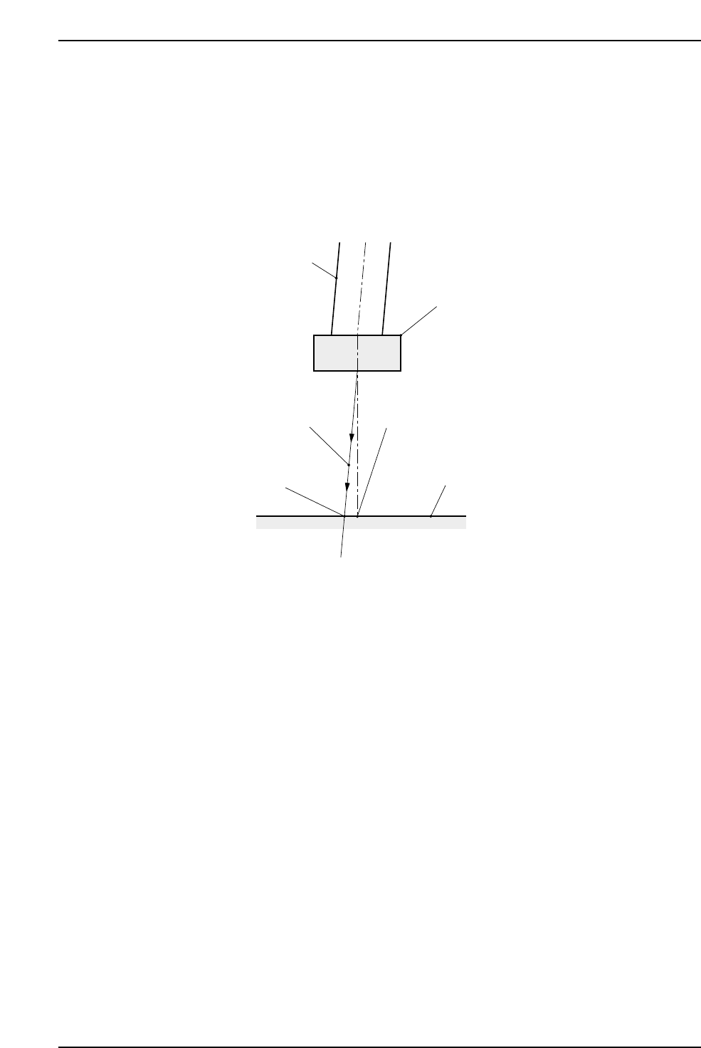
As shown in this illustration, when a nozzle cannot move in a completely vertical
direction due to mechanical errors, the center of a part, as seen by the vision processing
system, and the actual center may not correlate.
The measurement performed by PAM involves a process in which dummy chips are
actually placed on a mark reference board, with the chip placement accuracy being
checked by a mark camera. Each nozzle is rotated to 0 degrees, 90 degrees, 180 degrees,
and 270 degrees and the vision processing data for the placed parts then undergoes
statistical processing to provide an accurate measurement of the mechanical error
amount.
Nozzle
Decending
trajectory
Board
Part center detected
by Vision Processing
Part center
at placement
Part
C6PM1002
1. Using PAM
Version 3.0 1-2 CP-6 Series PAM Operation