CP6S-PAM操作手册.pdf - 第26页
Procedure at PC Setting the Communication Conditions 1. At the PC side, connect the transmission cable (machine <—> NTCC) to the port which is not being used by NTCC. If there are no vacant ports, leave the cable a…
Downloading Measurement Results to a PC
This procedure consists of downloading data lines, and it requires the following
environment.
• A Windows computer with NTCC installed.
• The Digi board (RS232C expansion port recommended by Fuji).
• Machine <—> PC transmission cable (Dwg. No. EEHH1061 or EEHH1071).
Procedure at Machine
1. Using the machine commands, proceed to “Page: Data Save-3”, then select the
[Change Port] command to specify the port (CH1 or CH2) where the data is to be
output.
2. Connect the transmission cable to the specified port.
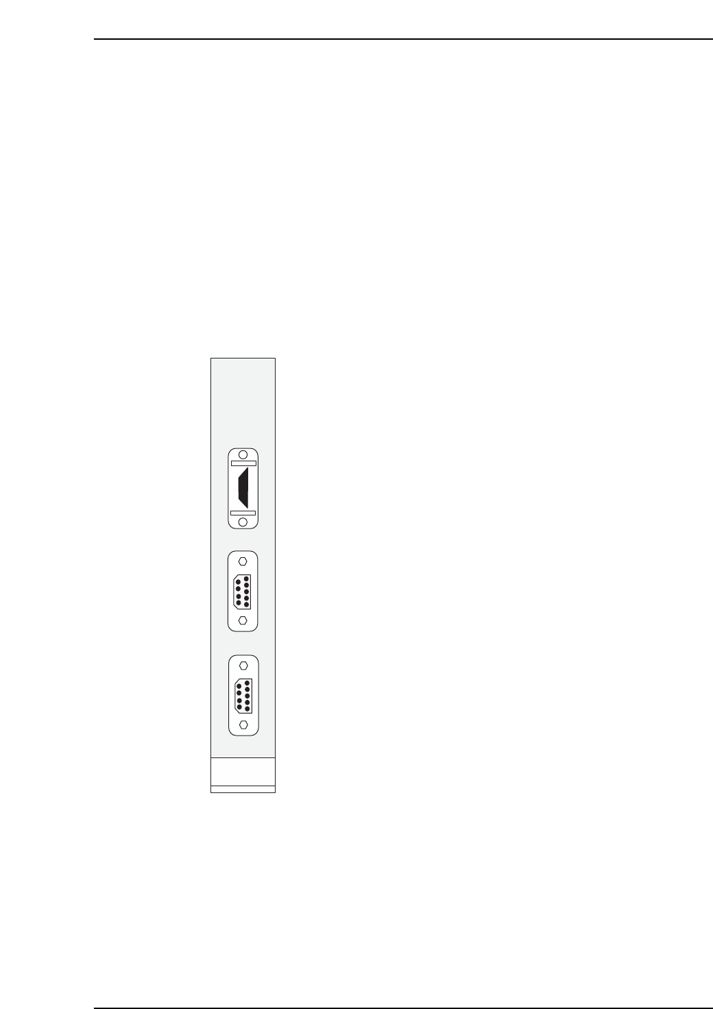
The machine’s CPU board is equipped with a printer port and 2
RS232C ports as shown at left.
The “RS232C 1” port is CH1.
The “RS232C 2” port is CH2.
When transmitting Proper data using an RS232C port, the data
line is connected from the machine’s side-face connector to CH1
by internal wiring. In this case, production information (PT) is
also sent to the host from CH1. The connector should therefore
be connected to CH2.
(Use the [Change Port] command to specify CH2)
When using the internal CC, either CH1 or CH2 may be used. In
this case, the machine <—> PC transmission cable must be
connected to the machine’s side-face connector. (Transmission
cable Dwg. No.: EEHH1061 or EEHH1071).
PRINTER
RS232C 1
RS232C 2
HIMV-134
C6PM3004
3. ST 11 Proper Data Setting Procedure
Version 3.0 3-5 CP-6 Series PAM Operation

Procedure at PC
Setting the Communication Conditions
1. At the PC side, connect the transmission cable (machine <—> NTCC) to the port
which is not being used by NTCC. If there are no vacant ports, leave the cable as it
is, and end NTCC. (When NTCC is ended, acquisition of production information
from other machines is disabled.)
2. When using WindowsNT3.51
(1) Start up the communication software at the PC as follows: “Program
Manager” —> “Accessories” —> “Terminal”.
(2) At the Terminal menu, select “Settings” —> “Communication Conditions”,
then specify the following settings:
Communication speed (bps): 9600
Flow control: Xon/off
Serial port: COM?
(PC port connected to transmission cable)
Data length: 8
Stop bit: 1
Parity: None
(3) At the menu, select [File] —> [Save As] to save the setting conditions.
(Once saved, these settings are convenient when using the trace port. e.g.,
trace.trm).
3. When using WindowsNT4.0
(1) Click the START button, select “Accessories”, then start up the Hyper
Terminal.
(2) Enter the name (e.g., trace) at the connection settings, select the icon, then
click OK.
(3) Select the PC port (COM?) where the transmission cable is connected, then
click OK.
(4) At the port settings, specify the same settings as those at 2.2 above, then
click OK.
(5) At the menu, select [File] —> [Save] to save the setting conditions. (A
shortcut is created at the START button. e.g., trace.ht)
Starting Communication
When using WindowsNT3.51
1. Start up the “Terminal” (not necessary if already running).
2. At the Terminal menu, select [File] —> [Open] to open the settings file saved at
2.3 in the above section. (Not necessary if the communication conditions have
already been set.)
3. Select [TRANSMIT] —> [TEXT FILE RECEPTION], then enter the name of the file
where the trace list is to be saved. After entering the file name, click OK to enable
reception.
4. When reception is completed, select [Exit] to quit the Terminal application.
When using WindowsNT4.0
1. Click the START button, select “Accessories”, then open the shortcut (e.g., trace.ht)
in Hyper Terminal which was saved at 3.5 above.
2. At the menu, select [Transfer] —> [Capture Text], then enter the name of the file
where the trace list is to be saved. After entering the file name, click OK to enable
reception.
3. When reception is completed, select [Transfer] —> [Capture Text] —> [Exit] to
quit the Terminal application.
3. ST 11 Proper Data Setting Procedure
Version 3.0 3-6 CP-6 Series PAM Operation
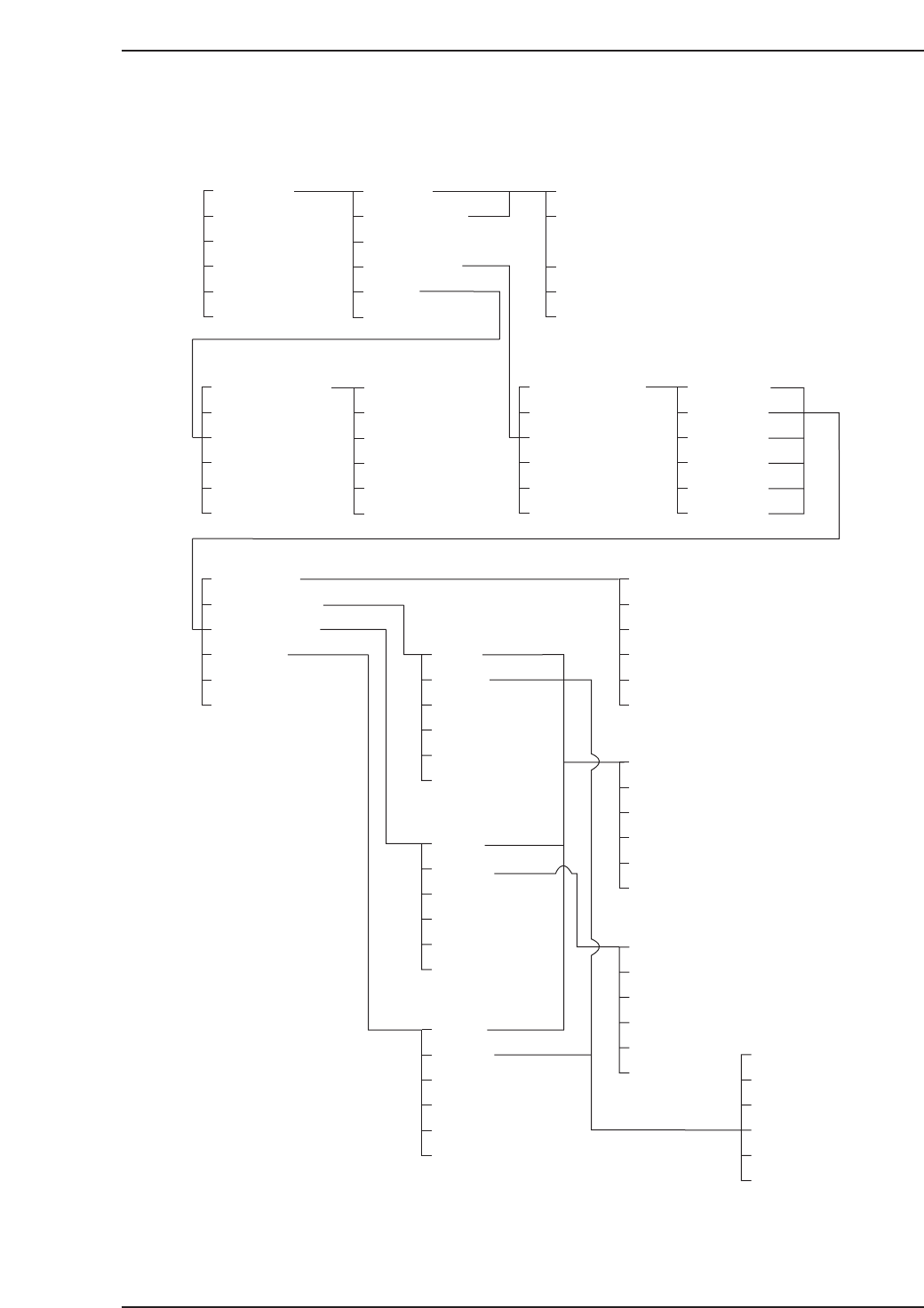
4. Command Hierarchy
PAM
LOADER
PROGRAM
SET
✶
000 100
Placing
Measurement
Data display
Editor
RETURN
110,120
Auto
Step
RETURN
✰ Press START
SIZE
SAVE
RETURN
150
▲
▼
Proper
Data input
Data Save
RETURN
151
SIZE
Data Save
RETURN
140
All deg.
0 deg.
90 deg.
180 deg.
270 deg.
RETURN
141
Deviation
Deviat'n avg.
Max/Min dev.
Accuracy
RETURN
+PAGE
-PAGE
Data Save
RETURN
141-1
141-1-1
Data Save
RETURN
141-1-2-1
+PAGE
-PAGE
Data Save
RETURN
141-1-2-2
+PAGE
-PAGE
Max value
Min value
Data Save
RETURN
141-1-3-2
141-1-2
141-1-3
141-1-4
Axis
Head
RETURN
Axis
Head
RETURN
Axis
Head
C6PM4001
RETURN
4. Command Hierarchy
Version 3.0 4-1 CP-6 Series PAM Operation