CP6S-PAM操作手册.pdf - 第45页
Pressing [All deg.] displays the deviation for the X, Y and Q-axes for all sequences placed with the nozzle type selected on command page 141. When [0 deg.], [90 deg.], [180 deg.], or [270 deg.] is selected, the deviatio…
The nozzle data selected on command page 140 displays here.
Function Key Menu
Monitor Display
Second Display Area
: READY
First Status Area : "No.1 NOZZLE", "No.2 NOZZLE", "No.3 NOZZLE"
"No.4 NOZZLE", "No.5 NOZZLE", "No.6 NOZZLE"
Function Key Operation
Deviation: Displays the nozzle deviation for each axis (X, Y and Q)
To page 141-1-1
Deviat’n avg.: Displays the nozzle deviation average for each head and specified
axis (X, Y or Q) To page 141-1-2
Max/Min dev.: Displays the max/min nozzle deviation amount for each head and
specified axis (X, Y or Q) To page 141-1-3
Accuracy: Displays the nozzle accuracy (3s) for each head and specified axis
(X, Y or Q) To page 141-1-4
RETURN: Returns to page 141 To page 141-1
Page141
CP_6.PROGRAM
000000000000
000000000000
Prod 00000 Sche 00000
P1.00 off line
Operation : Front
Ready
RETURN
jog
XY
C
Deviat'n avg.
Avg.dX
- 13
Max.dX
26
Max.dX
- 13
3sig.X
18
Avg.dQ
- 278
Max.dQ
476
Max.dQ
- 278
3sig.Q
483
- 9
Avg.dY
19
Max.dY
- 9
Max.dY
4
3sig.Y
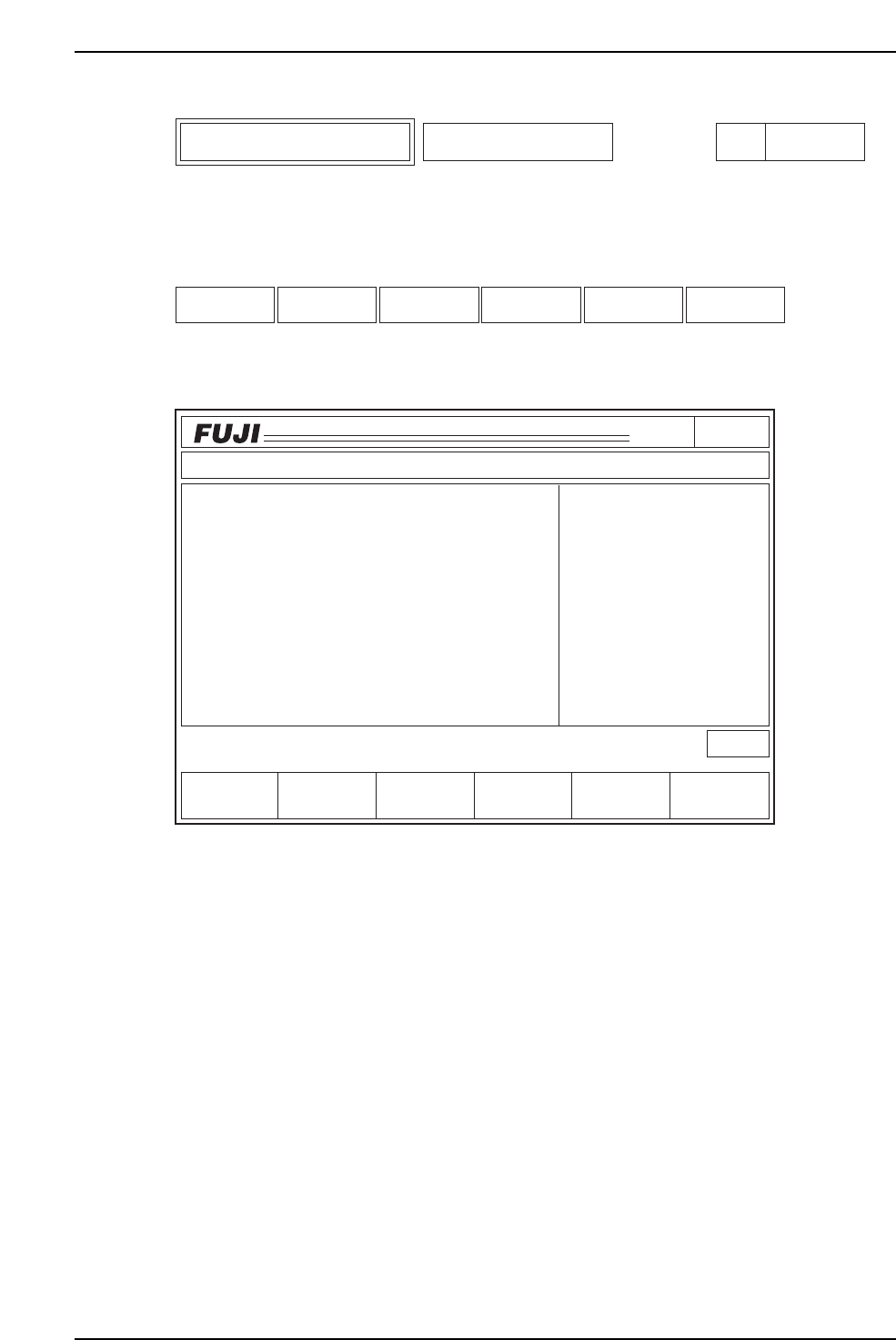
No.1 NOZZLE
Measurement Result
Nozzle Type
All Nozzle
All degrees
All data
5000
dXdY
[1/1000mm]
dQ
[1/1000deg]
Max/Min dev. AccuracyDeviation
C6PM6023
Deviation Deviat'n avg. Max/Min dev. Accuracy RETURN
Specific Nozzle Data Display
No.1 ~ No.6 NOZZLE
Page
141-1
6. Description of Commands
Version 3.0 6-12 CP-6 Series PAM Operation
Pressing [All deg.] displays the deviation for the X, Y and Q-axes for all sequences placed
with the nozzle type selected on command page 141.
When [0 deg.], [90 deg.], [180 deg.], or [270 deg.] is selected, the deviation for the X, Y
and Q-axes for all sequences placed with the selected nozzle types and placement angles
are displayed.
Function Key Menu
Monitor Display
• The selected nozzle data displays under the heading "Nozzle Type" at the upper
right of the first display area.
• The selected angle data is displayed under the heading "Nozzle Type".
• The units of measurement in the display are 1/1000 mm for dX and dY; and
1/1000° for dQ.
• The data used to calculate the deviation amount displays in the middle right of the
1st display area.
• "****" displays as an error message if a vision processing error occurs while the
software reads the placement data.
• Inputting a sequence number from the numerical keypad jumps the display to that
particular sequence.
Page141
CP_6.PROGRAM
000000000000
000000000000
Prod 00000 Sche 00000
P1.00 off line
Operation : Front
Ready
RETURN
jog
XY
C
-PAGE Data Save
Seq.
3
4
5
6
7
8
9
10
11
12
dX
DEVIATION
Deviations for each measuring point
Nozzle Type
No. 1
All degrees
All data
5000
dXdY
[1/1000 mm]
dQ
[1/1000 deg]
+PAGE
- 10
18
- 9
- 26
****
10
5
0
- 1
- 4
dY
- 1
3
4
- 7
****
- 1
2
5
- 3
- 6
dQ
90
- 320
100
489
****
- 789
545
798
- 743
754
C6PM6026
+PAGE -PAGE Data Save RETURN
Specific Nozzle Deviation Display
Deviation
Page
141-1-1
6. Description of Commands
Version 3.0 6-13 CP-6 Series PAM Operation

Second Display Area : READY
First Status Area : DEVIATION
Function Key Operation
+ PAGE: Displays the next page
- PAGE: Displays the previous page
Data Save: Prints the deviation information for the angle specified on page 141.
All the sequences placed with the selected nozzle size are sent to the
printer if [All deg.] is selected.
Selecting [0 deg], [90 deg.], [180 deg.] or [270 deg.] sends the deviation
values for the sequences placed with the selected nozzle size at the
specified angle to the printer.
The printed format is shown on the following page.
RETURN: Returns to page 141-1 To page 141-1
Print Format
The angle data displayed between "Nozzle Type" and "Data No." is what is sent to the
printer.
Deviation Nozzle type 1
All deg.
X, Y [1/1000 mm] Q [1/1000 deg]
dX, dY [1/1000 mm] dQ [1/1000 deg]
N3 X -10000 Y 10000 Q 9000 dX -10 dY -1 dQ 90
N4 X -10000 Y 10000 Q 9000 dX 18 dY 3 dQ -320
Note: "****" displays for the sequence data if a vision processing error occurs while the software
reads the placement data (dX, dY, dQ).
6. Description of Commands
Version 3.0 6-14 CP-6 Series PAM Operation