4OM-1050-002.pdf - 第20页
Nozzle for Dispense Gun DG10KIT T able 4A7 Standard Shape Part No. Remarks No.14 1 0 1 2 630 062 2591 (Color: Olive) No.18 1 0 0 1 630 062 2607 (Color: Green) No.19 0 1 1 2 630 062 2621 (Color: Brown) No.20 1 0 0 2 630 0…
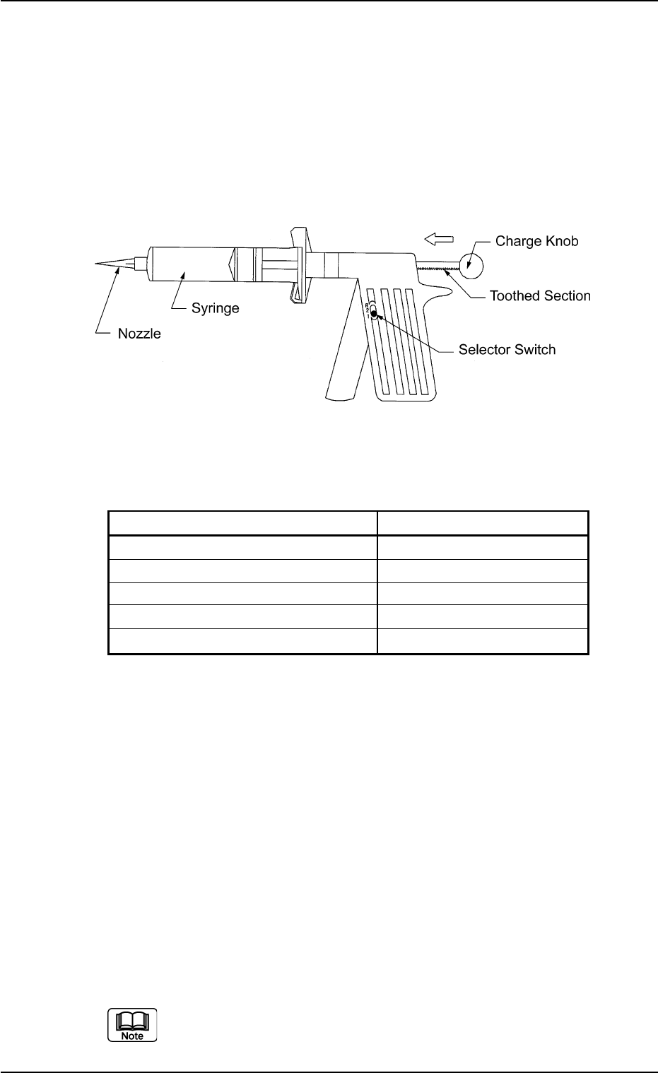
(6) Dispense Gun "DG10KIT"
Maker: Sanei Tech
This gun can be used for three types of greases.
Use the syringes and the nozzles properly.
Three Types of Greases: DAPHNE EPONEX GREASE No. 1
DAPHNE EPONEX GREASE No. 3
NEW MOLYNOC GREASE No. 1
Appearance
Fig. 4A4
<Contents of Kit>
Table 4A6
Part Name Q’ty
Dispense Gun (Main Body) for 10 cc 1
Syringe 20
Piston 20
End Cap 20
Syringe Cap 20
Usage
(6-1) Set the selector switch to "1" in normal cases.
Note: When the switch is set to "2", grease will be pushed out
excessively.
Be sure to set the switch to "R" before storing the gun (keeping it
unused).
(6-2) Before the charge knob is pushed to dispense the grease, con-
firm that the charge rod is inserted with its toothed section facing
downward.
(6-3) Check the amount of grease before it is supplied
(6-4) Push the charge knob slightly forward before the grease is sup-
plied.
Refer to the attached instruction manual for the detailed infor-
mation on how to use the dispense gun.
1.2 Preparation for Maintenance
01 10-003 1-6 AFO01ETRP
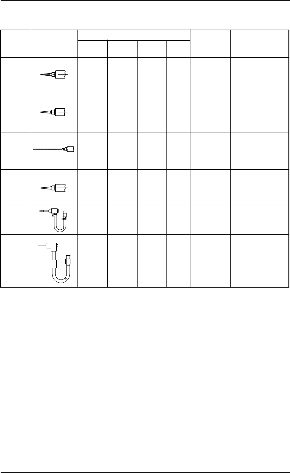
Nozzle for Dispense Gun DG10KIT
Table 4A7
Standard Shape Part No. Remarks
No.14 1 0 1 2 630 062 2591
(Color:
Olive)
No.18 1 0 0 1 630 062 2607
(Color:
Green)
No.19 0 1 1 2 630 062 2621
(Color:
Brown)
No.20 1 0 0 2 630 062 2614
(Color:
Pink)
HL2 Type 0 1 0 1 630 105 4445
RR Type 0 1 0 1 630 110 5307
Grease and Number of Required Nozzles
For DAPHNE
EPONEX
GREASE No. 1
For NEW
MOLYNOC
GREASE No. 1
Total
Frequency
in Use
For DAPHNE
EPONEX
GREASE No. 3
Maker: Sanei Tech
Inside Diameter: φ1.6
Tapered Nozzle
#5114TT-B
Maker: Sanei Tech
Inside Diameter: φ0.84
Tapered Nozzle
#5118TT-B
Maker: Nipro
Inside Diameter: φ0.79
Length: 65 mm
Flattened End
Maker: Sanei Tech
Inside Diameter: φ0.58
Tapered Nozzle
#5120TT-B
Maker: HTI
Maker: HTI
1.2 Preparation for Maintenance
0307-004 1-7 AFO01ETRP
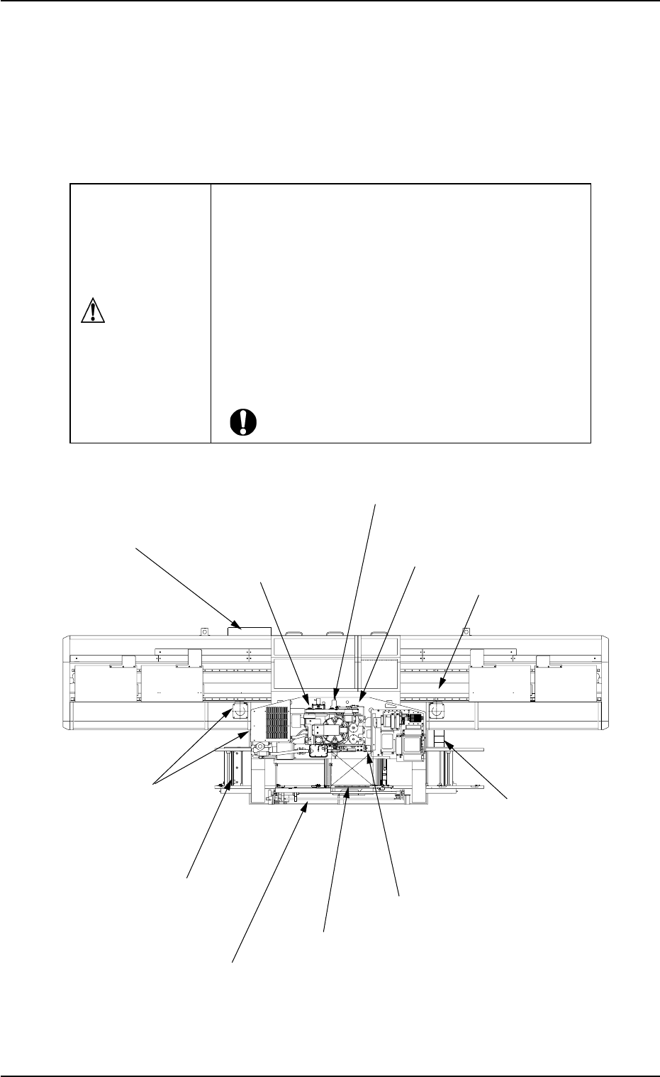
1.3 Maintenance Spots
1.3.1 General View
Refer to "1.3.2 Inspection, Cleaning, and Lubrication Spots" and after
for details.
Fig. 4A5 Top View of Machine
1.3 Maintenance Spots
0210-004 1-8 AFO01ETRP
(17) P.C.B. Transfer Section
(8) Light Source Device for
Component Recognition
(27) L/R Conveyor Sections
(26) Filters and
Fans in Each Section
(2) Vacuum System
(3) Dust Collector and
Waste Tape Box
(7) X/Y Table Section
(20) Placement Height Correction Section
(13) Feeder Carriage
Section
(22) Tape Feed Unit Section
(5) Intermediate Base
(18) Pick-Up Height
Correction Section
• Before performing maintenance work, turn off the
power and air sources and lock the power breaker
using the padlock.
• Designate a person who can have charge of the
padlock key.
• The cover of the machine must be detached for the
maintenance work.
After the maintenance work, be sure to attach the
cover.
CAUTION