4OM-1050-002.pdf - 第66页
(1-5) Detachment of V acuum Nozzle Push the bottom of the nozzle removal jig gently and set it on the vacuum nozzle such that the hook is engaged correctly with the two-plane cham- fered side of the vacuum nozzle. The no…
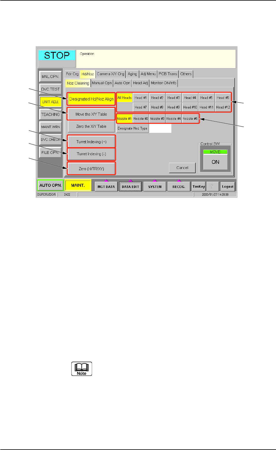
(1-2) Open the "Noz Cleaning" tab sheet. (Operation Sequence:
"UNIT ADJ." Window (Submenu) Æ "Nozzle Adj." Tab Æ
"Noz Cleaning" Tab Sheet)
Fig. 4A64 "Noz Cleaning" Tab Sheet
(1-3) Select the [Move the X/Y Table] button (*4) and press the
[ON] button (entitled "MOVE"). In 2 seconds, press the
[ENABLE] button on the operation panel.
The X/Y Table moves from the cleaning position to the es-
cape position.
(1-4) Select the [All Heads] button (*1) and specify the nozzle (*2)
to be detached.
Select the [Designated Hd/Noz Align] button (*3) and press
the [ON] button (entitled "MOVE"). In 2 seconds, press the
[ENABLE] button on the operation panel.
The nozzle is shifted to the position (the front side of the
machine) where it can easily be cleaned.
To detach a nozzle on the desired head, press the
corresponding [Head #] button.
1.4 Maintenance Method
0301-006 1-51 AFO01ETRP
*3
*4
*5
*6
*7
*1
*2
(1-5) Detachment of Vacuum Nozzle
Push the bottom of the nozzle removal jig gently and set it on the vacuum
nozzle such that the hook is engaged correctly with the two-plane cham-
fered side of the vacuum nozzle.
The nozzle removal jig cannot be used for nozzle type 031 (f6
nozzle). Detach the nozzle by hand.
Fig. 4A65
(1-6) Pull down the nozzle removal jig to detach the vacuum nozzle.
(a) Do not score the diffusion plate while detaching a
vacuum nozzle.
(b) A miniature stroke bearing is used at the nozzle
up/down movement section which consists of the
shaft, the retainer cage, and the external cylinder
units.
When the section is disassembled by mistake,
be sure to correctly reassemble each unit which
belongs to the section.
When the nozzle is detached, the miniature stroke
bearing and the shaft section should not be re-
moved.
Fig. 4A64-1
Avoid getting the removed vacuum nozzle
magnetized.
When the nozzle is magnetized, an error will occur
in component pick-up or placement.
CAUTION
Fig. 4A66
1.4 Maintenance Method
0301-005 1-52 AFO01ETRP

(1-7) To detach the nozzle on the subsequent head, select the [Tur-
ret Indexing (+)] button (*5) and press the [ON] button (entitled
"MOVE"). In 2 seconds, press the [ENABLE] button on the
operation panel.
The rotary turret starts rotating and the subsequent head
moves to the nozzle detachment position.
Repeat the steps, starting with Step (1-5) until all nozzles are
detached.
When the rotary turret is rotated with a nozzle being
attached, select the [Turret Indexing (-)] button and
press the [ON] button (entitled "MOVE"). The rotary
turret rotates backward by 1 pitch.
1.4 Maintenance Method
0301-006 1-53 AFO01ETRP