4OM-1050-002.pdf - 第82页
Fig. 4A84-1-1 (5) Detach the lower blade by removing Bolts C (M5 × 12). When the lower blade cannot be detached easily , try to pull it right and left alternately . (6) Attach a new lower blade and secure it with Bolts C…
1.4.7 Replacement of Cutter Blade
Time of Replacement
Replace a cutter blade with a new one when the cutting quality has
deteriorated due to wear, cracks, etc.
Replacement Procedure
(1) Zero the feeder carriage and turn off the power supply.
(2) Open the central safety guard of the feeder unit.
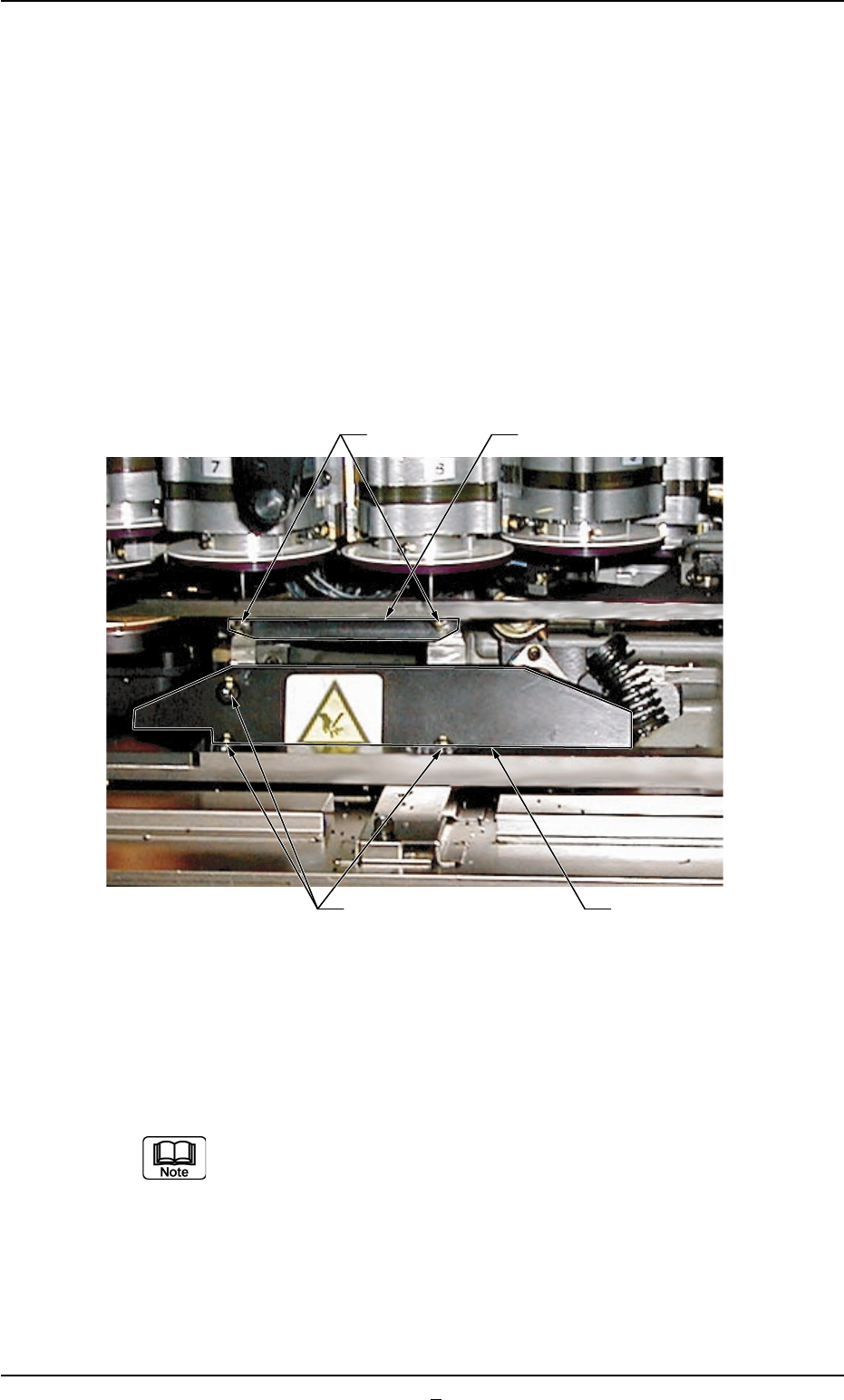
(3) Detach the upper blade by removing Bolts A (M5 × 16).
Fig. 4A84-1
(4) Remove SEMS-BOLT B (M5 × 12) fastening the lower blade holding
plate with the torque L-type wrench (Standard Accessory Part: 630
063 9759) and detach the plate.
While detaching the lower blade holding plate, be careful not
to touch the nozzles and diffusion plates. Also, avoid hitting
them with a tool.
0301-005 1-66 AFO01ETRP
1.4 Maintenance Method
Upper Blade
Lower Blade Holding Plate
Bolts A
Bolts B
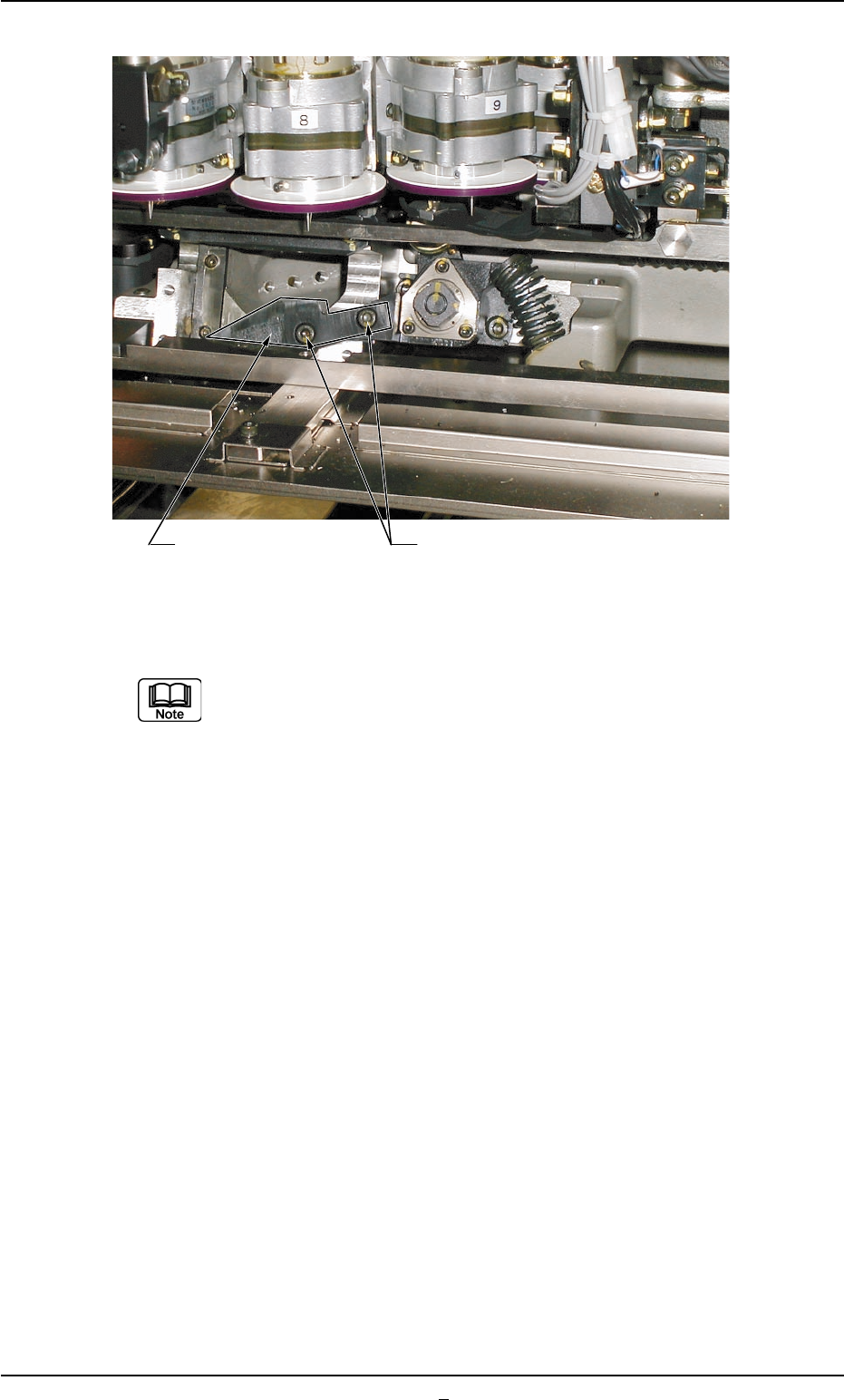
Fig. 4A84-1-1
(5) Detach the lower blade by removing Bolts C (M5 × 12).
When the lower blade cannot be detached easily, try to pull it
right and left alternately.
(6) Attach a new lower blade and secure it with Bolts C (M5 × 12).
(7) Attach the new lower blade holding plate and secure it with SEMS-
BOLT B (M5 × 12).
(8) Attach a new upper blade and secure it with Bolts A (M5 × 16).
(9) Turn on the power supply of machine and confirm that the rotary
turret works normally, using "Smooth Manual Axis Operation (Low
Speed)" for the rotary turret.
Refer to "2.2.1 "Rotary Turret" Tab" in "Section 6 (Vol. 2)" for details.
1.4 Maintenance Method
Lower Blade Bolts C
0301-001 1-66-1 AFO01ETRP
1.4 Maintenance Method
0307-005 1-67 AFO01ETRP
1.4.8 Lubrication of Linear Guide in Feeder Carriage Section
Grease should be applied every 6 months after the initial month.
••
••
• Preparation for Lubrication
(1) Turn off the power supply to the machine and wipe off old grease
on the rail of the linear guide with a rag.
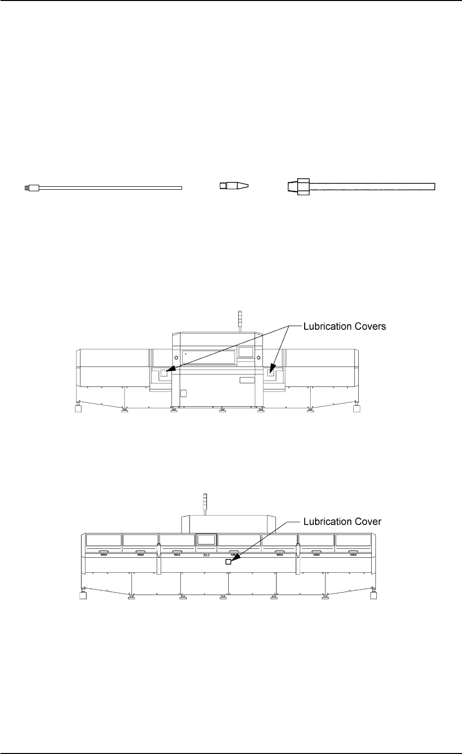
(2) Prepare the FL- and P-type or the U- and P-type attachments.
Fig. 4A84-2
(3) Detach the lubrication covers from the front and rear sides of
the machine.
Fig. 4A84-3 Front Side of Machine
Fig. 4A84-4 Rear Side of Machine
FL Type
P Type
U Type