Manual_BSA_II_英文操作说明书.pdf - 第10页
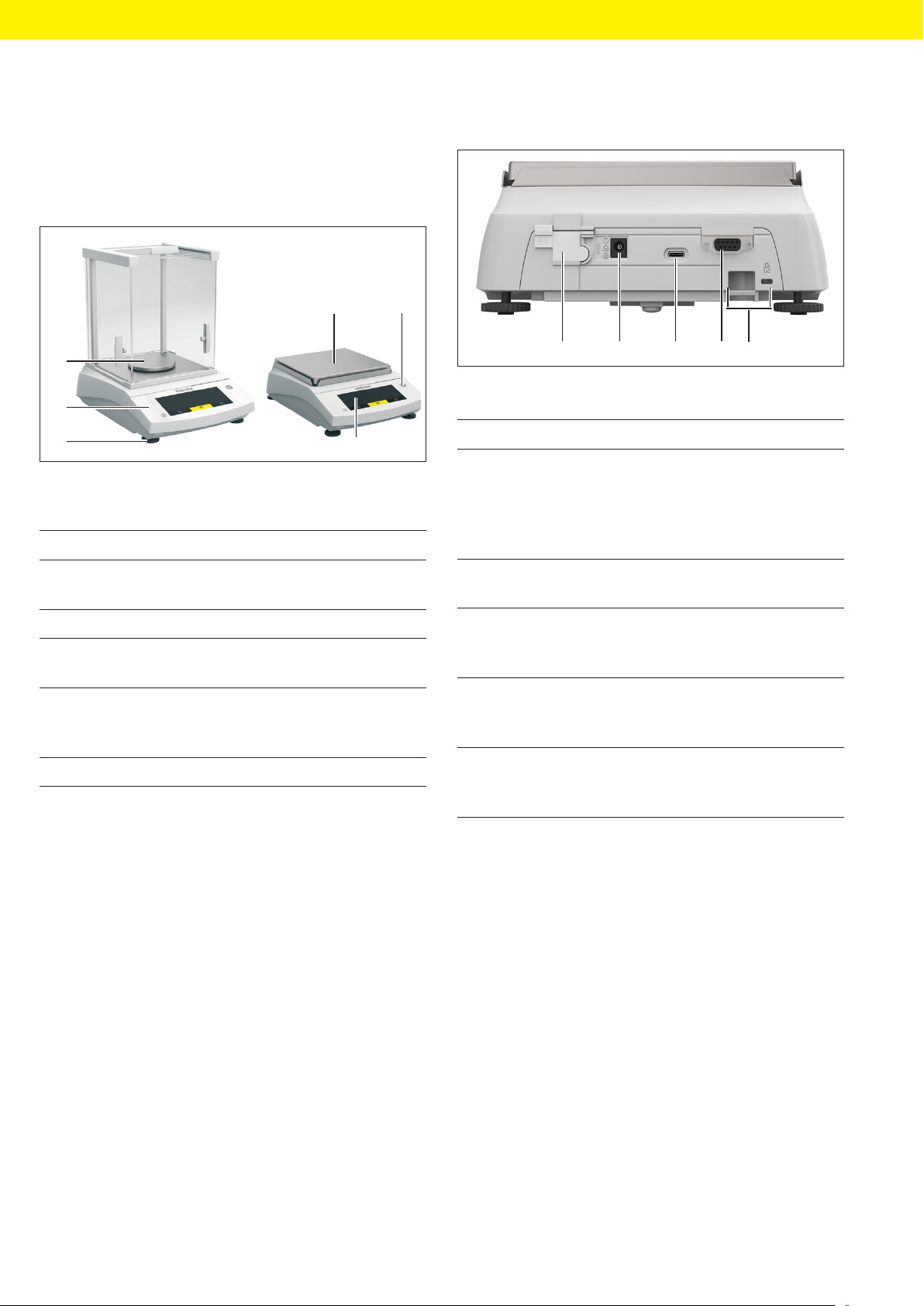
10 BSA II Operating Instructions Device Description 3 Device Description 3.1 Device Overview 2 3 5 4 1 1 Fig. 1: Device with analytical draft shield and device with frame draft shield (example) P os. Name Description 1 W…

BSA II Operating Instructions 9
Safety Instructions
2.5 Conduct in an Emergency
If an emergency occurs, e.g., due to malfunctions of the
device or dangerous situations: Persons may be injured.
The device must be immediately taken out of operation:
t Disconnect the device from the power supply.
t Prevent the device from recommissioning.
2.6 Accessories
The use of unsuitable accessories can affect the func-
tionality and operating reliability of the device and have
the following consequences:
− Risk of injury to persons
− Damage, malfunctions, or failure of the device
t Only use accessories that have been approved by
Sartorius for this device.
2.7 Risk of Injury When Carrying
the Device
If the device is not carried correctly:
− Fingers could get caught in the draft shield.
− The device could fall and cause an injury, e.g. a foot
injury.
− The device connections could be damaged.
t Use both hands to carry the device. To do this, reach
sideways under the device with both hands.
t Do not carry the device on the draft shield or the
control unit.
t Disconnect the device from all connections at the in-
stallation site.
2.8 Glass Breakage
Glass components can break if they fall or are handled
incorrectly. Glass fragments can cause cuts.
t In the event of damage to the operating display or
draft shield, do not use the device. Contact Sartorius
Service.
t Only operate the operating display with your fingers.
Do not use pointed or sharp objects.
10 BSA II Operating Instructions
Device Description
3 Device Description
3.1 Device Overview
2
3
5
4
1
1
Fig. 1: Device with analytical draft shield and device with frame draft
shield (example)
Pos. Name Description
1 Weighing pan Intended for placing the
sample
2 Level
3 Operating dis-
play
4 Leveling foot Used to level the bal-
ance, manually adjust-
able
5 Control unit
3.2 Device Connections
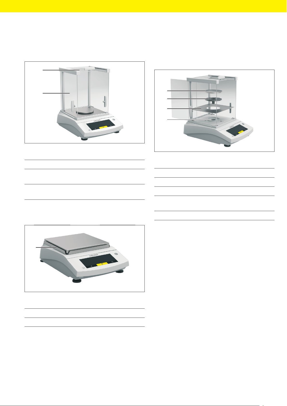
1 2 3 4 5
Fig. 2: Device with frame draft shield (rear view)
Pos. Name Description
1 Access switch Protects the device from
changes to the device
settings. Is sealed for
conformity-assessed de-
vices.
2 Power supply Connection for power
supply to the device
3 USB-C connec-
tion
For connection to a
printer, PC, or a second
display
4 RS232 connec-
tion
9-pin, for the connection
to a printer, PC, or a sec-
ond display
5 Slot For attaching an an-
ti-theft device or a Kens-
ington lock
BSA II Operating Instructions 11
Device Description
3.3 Draft Shield
3.3.1 Analytical Draft Shield
1
2
Fig. 3: Device with analytical draft shield (example)
Pos. Name Description
1 Upper draft
shield panel
Used to open the upper
panel manually
2 Side draft shield
panel
Used to open the side
panel manually
3.3.2 Frame Draft Shield
1
Fig. 4: Device with frame draft shield (example)
Pos. Name
1 Frame draft shield
3.4 Weighing Pan and Associated
Components
3.4.1 Devices with Analytical Draft Shield
1
2
3
4
Fig. 5: Device with analytical draft shield (example)
Pos. Name Description
1 Weighing pan
2 Pan support
3 Base plate Can be taken out, e.g. for
cleaning.
4 Pan retainer