Manual_BSA_II_英文操作说明书.pdf - 第43页
BSA II Operating Instructions 43 T echnical Data 15.2 Dimensions for Devices with F rame Draft Shield 4 3 2 1 1 Fig. 10: Device with analytical draft shield (side view and top view) P os. Description Unit V alue 1 W eigh…
42 BSA II Operating Instructions
Technical Data
15 Technical Data
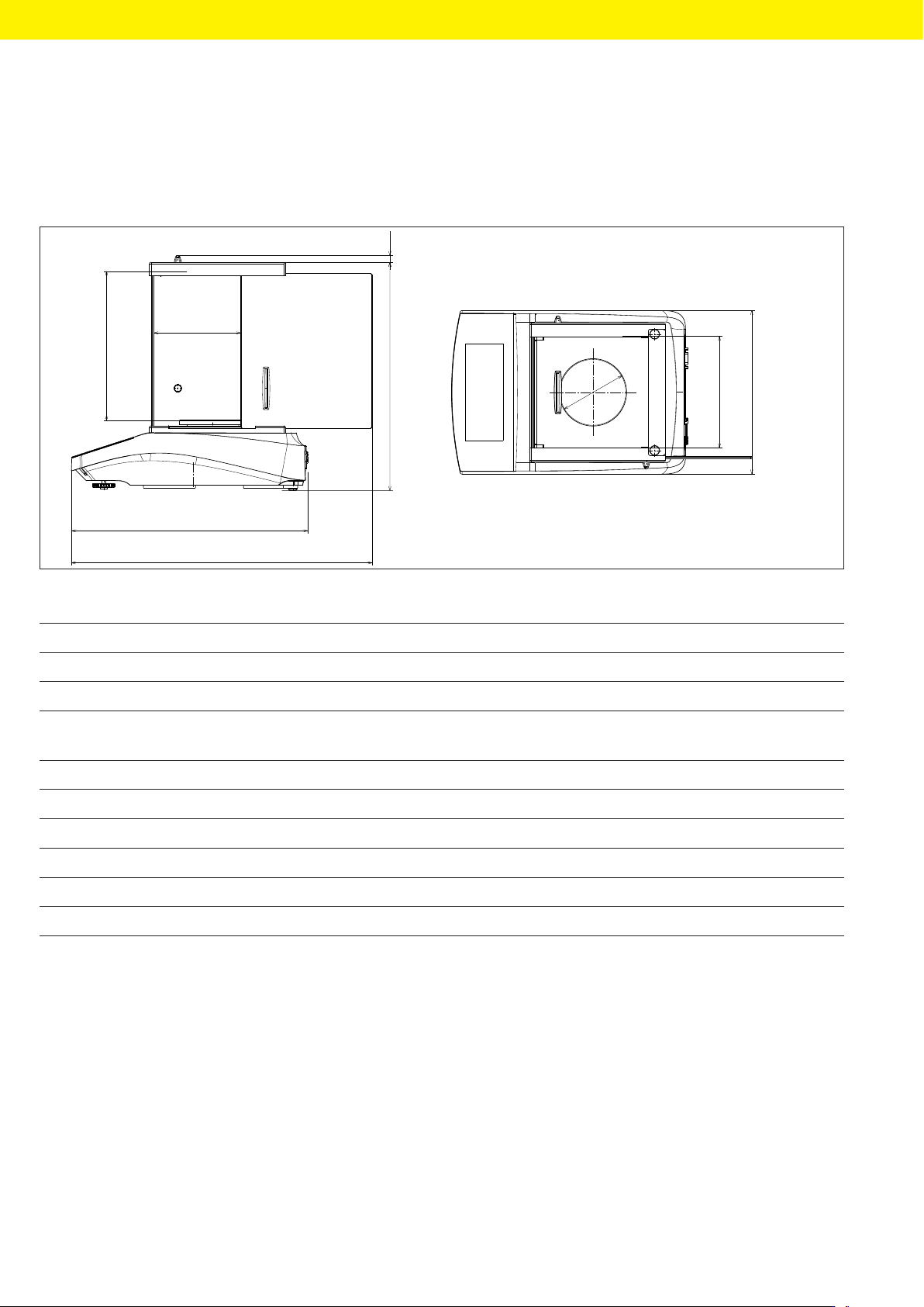
15.1 Dimensions for Devices with Analytical Draft Shield
5
6
4
3
9
2
1
7
8
Fig. 9: Device with analytical draft shield (side view and top view)
Pos. Description Unit Value
1 Usable height in weighing chamber mm 200
2 Maximum opening width of side door mm 115
3 Weighing pan size (diameter) for devices with analytical draft
shield, with readability 0.1 mg | 1 mg
mm 90 | 120
4 mm 150 ± 2
5 mm 9
6 mm 306 ± 2
7 mm 317 ± 2
8 mm 402 ± 2
9 mm 219 ± 2
BSA II Operating Instructions 43
Technical Data
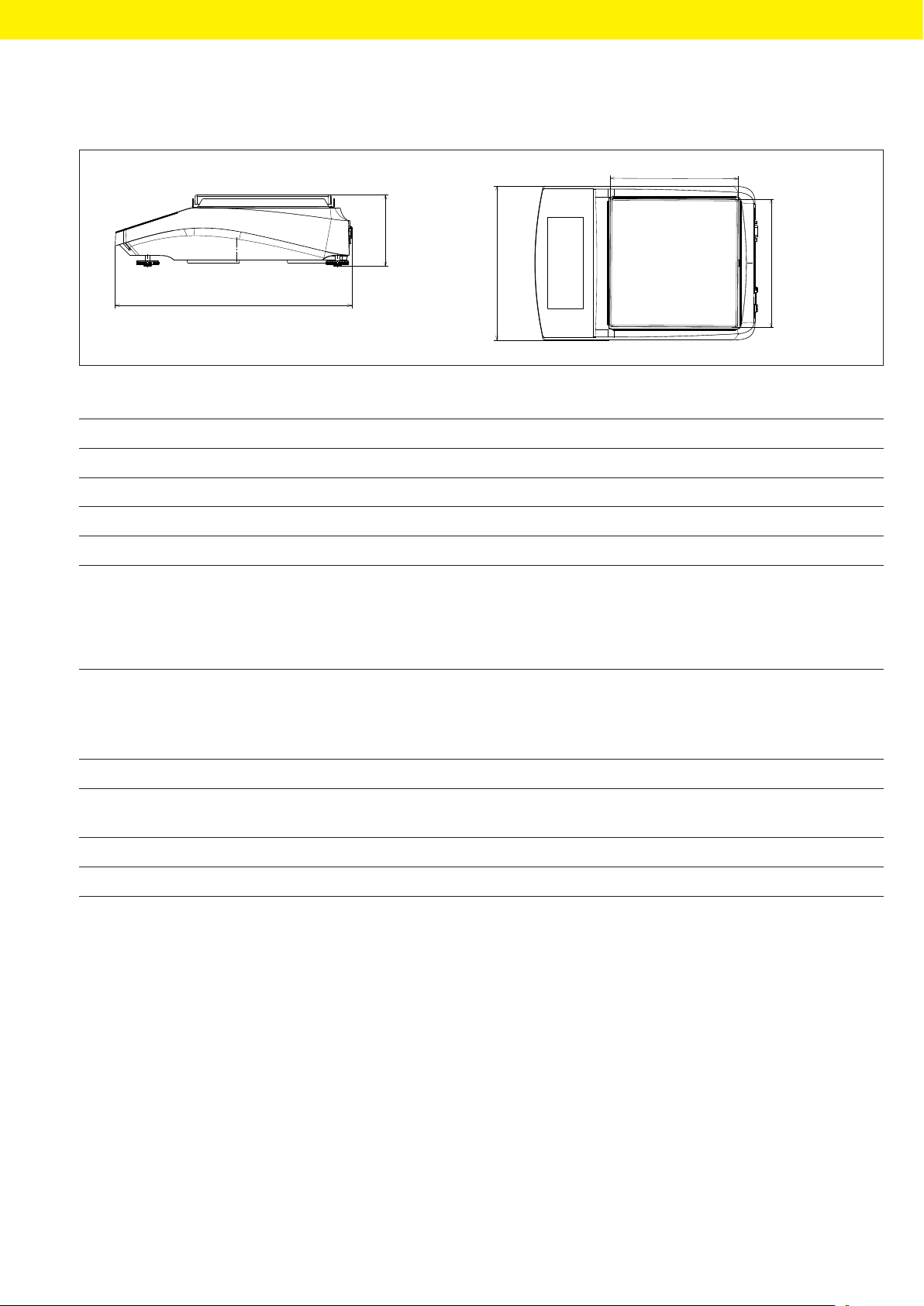
15.2 Dimensions for Devices with Frame Draft Shield
4
3
2
1
1
Fig. 10: Device with analytical draft shield (side view and top view)
Pos. Description Unit Value
1 Weighing pan size (L × W) mm 182 ± 1
2 mm 219 ± 2
3 mm 94 ± 5
4 mm 317 ± 2
15.3 Weights
Devices with an-
alytical draft
shield, with read-
ability 0.1 mg
Devices with an-
alytical draft
shield, with read-
ability 1 mg
Devices with
frame draft
shield
Unit Value Value Value
Weight, including weighing pan and
associated components
Model 1x kg 5.9 5.9 4.3
Model I-1x kg 6.2 6.3 6.2
44 BSA II Operating Instructions
Technical Data
15.4 Ambient Conditions During Storage and Transport
Unit Value
Temperature
During storage and transport °C -10 – +60
Storage, dry
15.5 Installation Conditions
15.5.1 Installation Site
Unit Value
Height above sea level, maximum m 3000
No potentially explosive atmospheres
Pollution level at the installation site according to DINEN61010-1 2
Access to operation-relevant parts is guaranteed
Space requirements
Suitable for the dimensions of the device and the associated compo-
nents
Setup surface
Suitable for the weight of the device and the associated components
Additional properties
No heat from heating systems or direct sunlight
No electromagnetic fields or electromagnetic radiation, e.g., from radio
equipment
15.5.2 Ambient Conditions at the Installation Site
Unit Value
Temperature
In operation °C +5 – +40
In operation, for conformity-assessed (verified) balances in accordance
with country-specific approval, refer to the information on the balance.
°C +5 – +30
Relative humidity
At temperatures up to 31°C, maximum % 15 – 80
Then linear decrease from max. 80% at 31°C to max. 50% at 40°C
For conformity-assessed (verified) balances in accordance with coun-
try-specific approval, the legal regulations apply.