Manual_BSA_II_英文操作说明书.pdf - 第29页
BSA II Operating Instructions 29 Installation 5 Installa tion 5.1 Scope of Delivery Item Quantity Device 1 Devices with analytical draft shield: W eighing pan 1 P an support 1 Base plate 1 Analytical draft shield* 1 Devi…

28 BSA II Operating Instructions
Operating Design
4.6.16 “APPLIC.“/“STATIST.“ Menu
Parameters Settings Explanation
PRT.COMP. OFF Deactivates the component printout.
ON* Activates the component printout.
TAR.STAT. OFF* Deactivates automatic taring after the components are saved.
ON Activates automatic taring after the components are saved.
* Factory setting
4.6.17 “INPUT“ Menu
Parameters Settings Settings Explanation
DEV. ID Max 14 charac-
ters 09-0, A-Z, - ,
empty
Saves the entered ID number for the device.
DATE Saves the entered date.
TIME Saves the entered time.
SERV. PW. Max 7 charac-
ters 09–0, A–Z,
- , empty
Activates service mode.
INTERV. The SBI output rate can be set from 0 - 9999 seconds.
4.6.18 “LANGUAG.“ Menu
Parameters Settings Explanation
LANGUAG. ENGLISH*,
DEUTSCH,
FRANC.
ITAL.,
ESPANOL,
PORTUG.,
РYССKИИ,
POLSKI
Defines the menu language.
* Factory setting
BSA II Operating Instructions 29
Installation
5 Installation
5.1 Scope of Delivery
Item Quantity
Device 1
Devices with analytical draft shield:
Weighing pan 1
Pan support 1
Base plate 1
Analytical draft shield* 1
Devices with frame draft shield:
Weighing pan 1
Shock absorber 4
Transport lock* 2
Devices with analytical draft shield:
Dust cover
1
Power supply unit YEPS01-15VOW,
with country-specific power plug
adapters YEPS01-PS8, YEPS01-PS9,
YEPS01-PS10
1
Operating Instructions 1
*Mounted on delivery
5.2 Selecting an Installation Site
Procedure
t Ensure that the installation conditions have been
met (see Chapter 15.5, page44).
5.3 Unpacking
Procedure
t Open the package.
t Remove the top layer of foam packaging.
t
CAUTION Risk of injury when carrying the device!
t Grip the device underneath at the sides with both
hands and lift the device out of the bottom layer
of foam packaging.
t Do not grip the device on the draft shield or the
control unit.
t CAUTION Risk of injury from cuts due to broken
glass edges! In the event of damage to the operating
display or draft shield, do not use the device. Contact
Sartorius Service.
t Place the device down on a stable, completely flat
surface at the installation site.
t Remove the weighing pan and associated compo-
nents from the packaging.
t Keep all parts of the original packaging, e.g., to return
the device.
5.4 Installing a Device with an
Analytical Draft Shield
Procedure
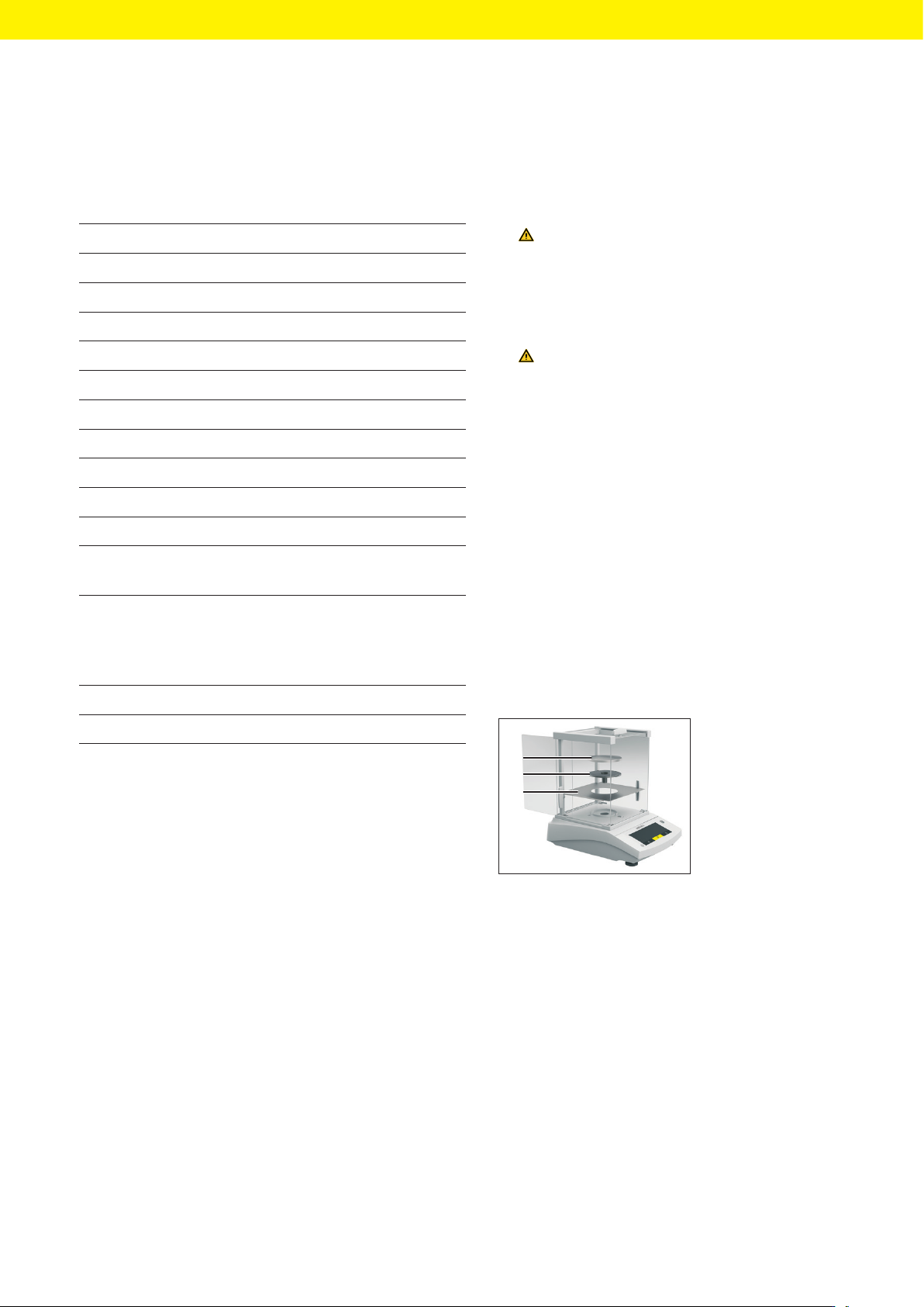
1
2
3
t Open one side panel
completely.
t Insert the base
plate(1).
t Fit the pan sup-
port(2) on the pan
retainer.
t Place the weighing
pan(3) on top.
30 BSA II Operating Instructions
Commissioning
5.5 Installing a Device with a
Frame Draft Shield
5.5.1 Removing the Transport Lock
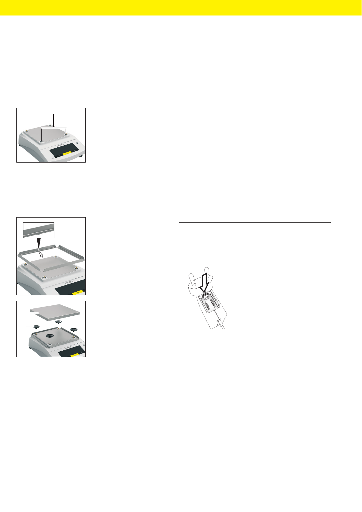
Procedure
1
t Remove the transport
locks (1) and retain
them for later use.
5.5.2 Mounting the Device
Procedure
t Insert the latch in the
recess.
t Rest the frame draft
shield completely on
top.
2
1
t Fit all shock absorb-
ers(2).
t Place the weighing pan
(1) on top.
5.6 Acclimatizing
When a cold device is brought into a warm environment:
The temperature difference can lead to condensation
from humidity in the device (moisture formation). Mois-
ture in the device can lead to malfunctions.
Procedure
t Allow the device to acclimatize to the installation
site. The device must be disconnected from the pow-
er supply during that time.
6 Commissioning
6.1 Mounting the Power Supply
Unit
6.1.1 Inserting the Power Plug Adapter
Item number
on packaging
Power supply unit YEPS01-
15VOW with connection cable
and country-specific power plug
adapters (packed in PE bag with
printed country identification, e.g.
EU)
YEPS01-PS8 USA and Japan (US+JP), Europe
and Russia (EU+RU), Great Britain
(UK), India (IN), South Africa (ZA),
Australia (AU), China (CN)
YEPS01-PS9 Argentina (AR), Brazil (BR), Korea
(KR)
YEPS01-PS10 China (CN)
Procedure
t Select the country-spe-
cific power plug adapter.
The power plug adapter
must be suitable for use
with the wall outlet at
the installation site.
t Insert the power plug adapter into the power supply
unit. The grooved button must be facing upwards.
t Push the power plug adapter as far as you can until it
audibly clicks into place.
t Check whether the power plug adapter is securely
locked in place by pulling it gently.
y If the power plug adapter does not move: The power
plug adapter is locked.