IPC-TM-650 EN 2022 试验方法1.pdf - 第246页
IPC-TM-650 Figure 1 Keyhole T est Plate 8.5 cm ± 0.13 cm ‘‘A” ‘‘A” 3.8 cm ± 0.25 cm 2 cm ± 0.25 cm 13.5 cm ± 0.25 cm 8 cm ± 0.25 cm 1.9 cm Blend entry edge of hole into bevel of slot 0.4 cm ± 0.013 cm (Slot) R 0.3 cm thi…
Figure 1 Multiple Failure Modes
Peel Distance
Load
High Peel Strength
Failure Mode
Low Peel Strength
Failure Mode
IPC-TM-650
Number
Subject Date
Revision
Page 3 of 3
IPC-TM-650
Figure 1 Keyhole Test Plate
8.5 cm
± 0.13 cm
‘‘A” ‘‘A”
3.8 cm ± 0.25 cm
2 cm
± 0.25 cm
13.5 cm
± 0.25 cm
8 cm ± 0.25 cm
1.9 cm
Blend entry edge of
hole into bevel of slot
0.4 cm ± 0.013 cm (Slot)
R
0.3 cm thick
AL Alloy
AA6061 T651
Pl
18 ± 2
0.41 cm Ref.
Section “A”-“A” Bevel detail 4x
+ 0.02 cm
- 0.013 cm
dia. hole
o
o
Page 1 of 3
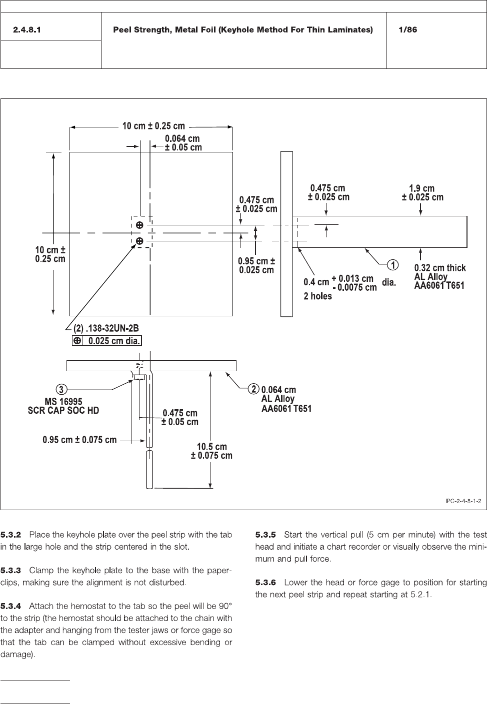
Figure
2 Keyhold Horizontal Axis
GI
IPC-TM-650
Number
Subject Date
Revision
Page 2 of 3