IPC-TM-650 EN 2022 试验方法1.pdf - 第793页
Figure 3 T olerances for Half Sine Shock Pu lse IPC-TM-650 Page 4 of 5
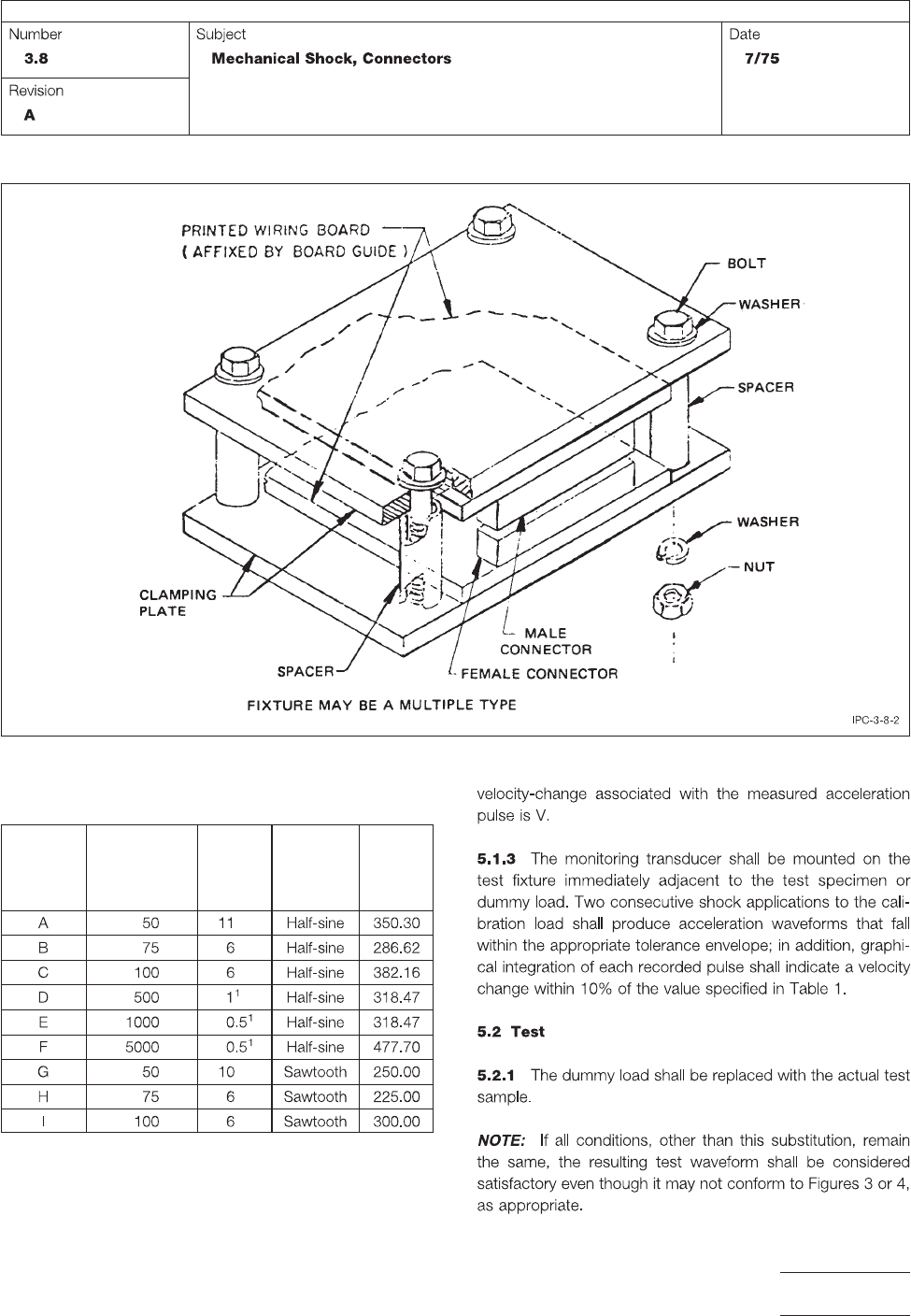
Figure 2 Parallel Connector Fixture (Suggested)
Table I
Test Conditions
Test
Condition
Peak
Acceleration
A-Gravity
Units
Nominal
Duration
D-Milli-
seconds Waveform
Velocity
Change
Vi
(G-MS)
IPC-TM-650
Page 3 of 5
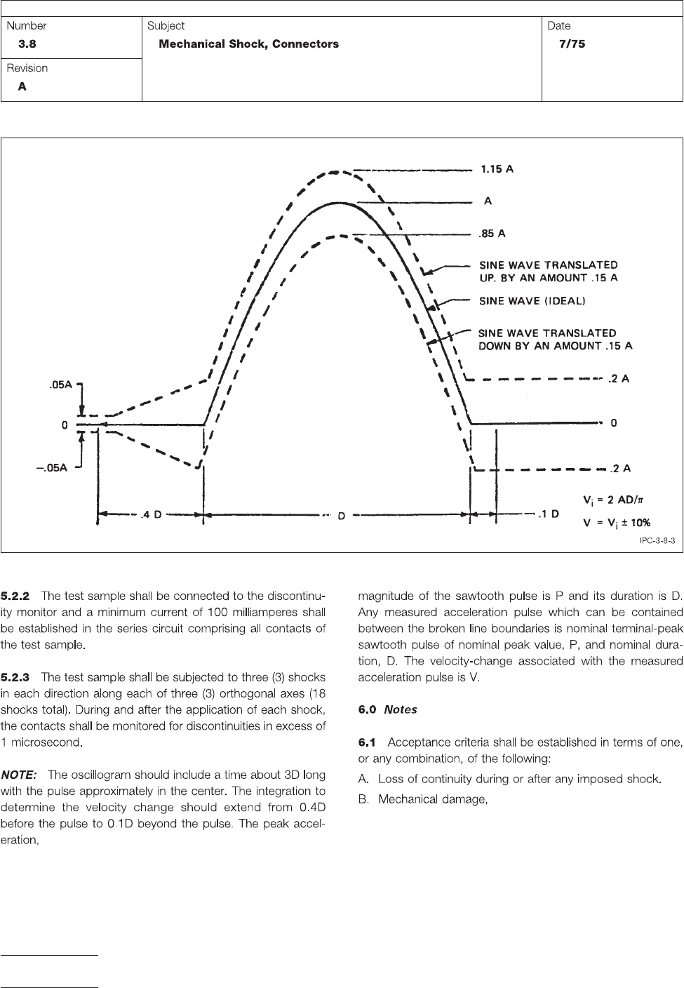
Figure 3 Tolerances for Half Sine Shock Pulse
IPC-TM-650
Page 4 of 5
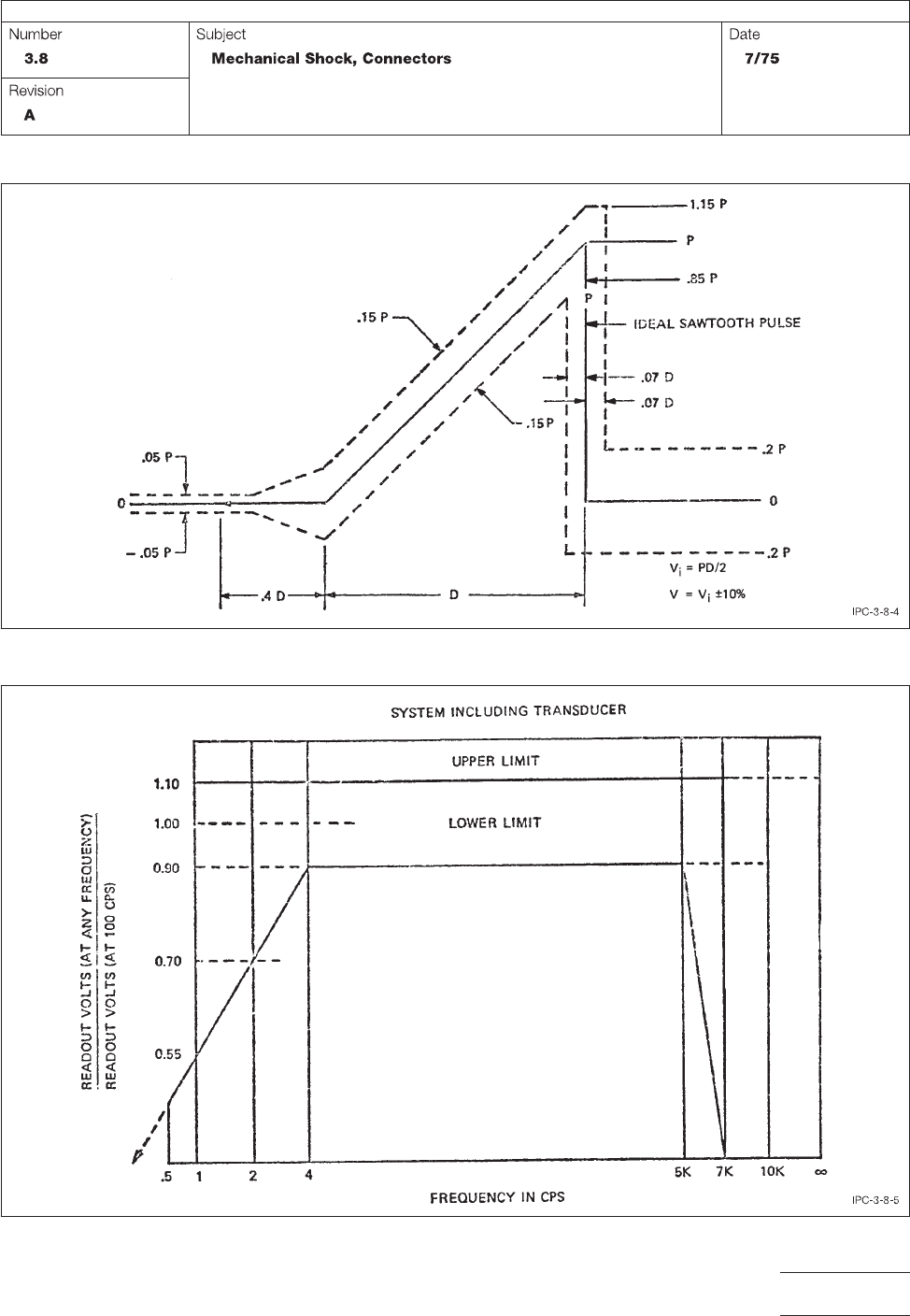
Figure 4 Tolerances for Terminal-Peak Sawtooth Shock Pulse
Figure 5 Tolerance Limits for Measuring System Frequency Response
IPC-TM-650
Page 5 of 5