IPC-TM-650 EN 2022 试验方法1.pdf - 第463页
Figure 6 Clam p Arrangement (See 5.1.5) Showing Side and Fr ont Views for Specimen Lengths of 76.2 mm a nd 304.8 mm Figure 7 Copper Fitting w ith Reverse Be vel (See 5.2.2) Soldered to t he 1.8 mm Semi-Rigid Coaxial Cabl…
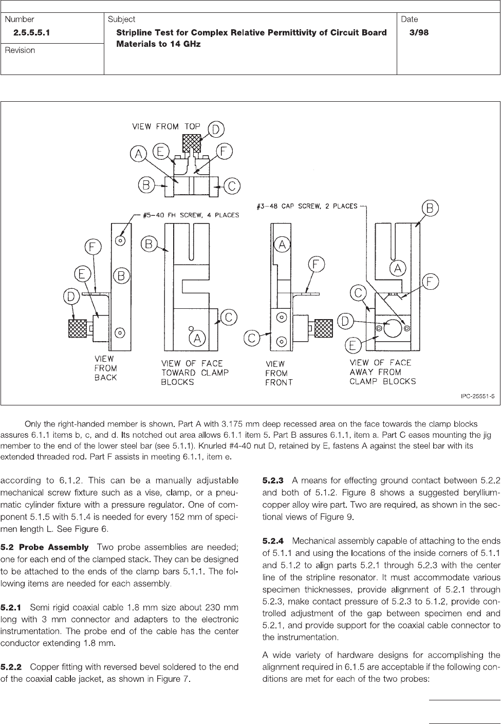
Figure 5 Five Assembly Views for a Suggested Two Member Stacking Alignment Jig (See 5.1.3)
Note:
IPC-TM-650
Page 5 of 11
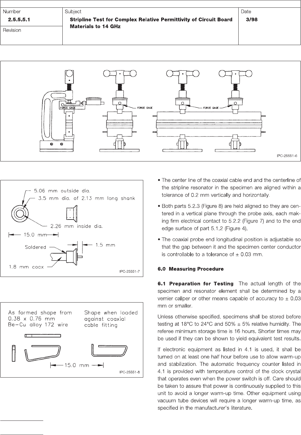
Figure 6 Clamp Arrangement (See 5.1.5) Showing Side and Front Views for Specimen Lengths of 76.2 mm and 304.8 mm
Figure 7 Copper Fitting with Reverse Bevel (See 5.2.2)
Soldered to the 1.8 mm Semi-Rigid Coaxial Cable Probe
Figure 8 Formed Be-Cu Alloy Wire for Ground Continuity
from Coaxial Cable Fitting to Copper Ground Plate
IPC-TM-650
Page 6 of 11
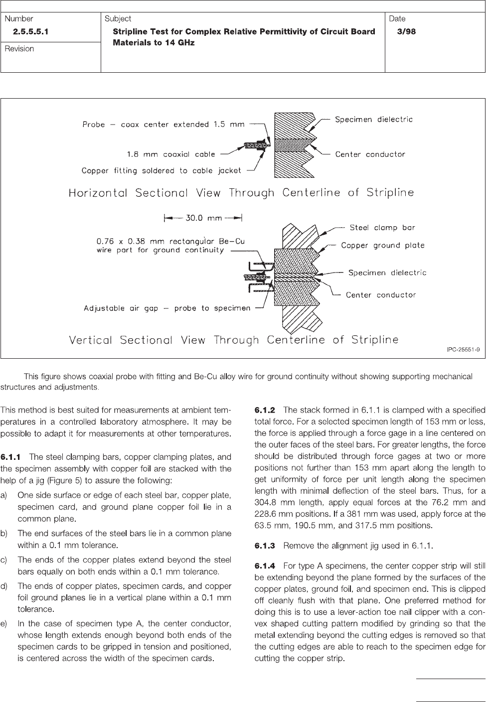
Figure 9 Probe Assembly Position (See 6.1.5) for One End of the Clamped Stack
Note:
IPC-TM-650
Page 7 of 11