IPC-TM-650 EN 2022 试验方法1.pdf - 第535页
3 . 9 0 10 20 Frequency (GHz) 30 40 50 3 . 8 5 3 . 8 0 3 . 7 5 3 . 7 0 Relative Permittivity 10 G Hz S pl i t- Cy l in de r R es o nat o r 35 GH z S pl i t- Cy l in de r R es o nat o r T E 0 1 1 T E 0 1 3 T E 0 2 1 T E 0…
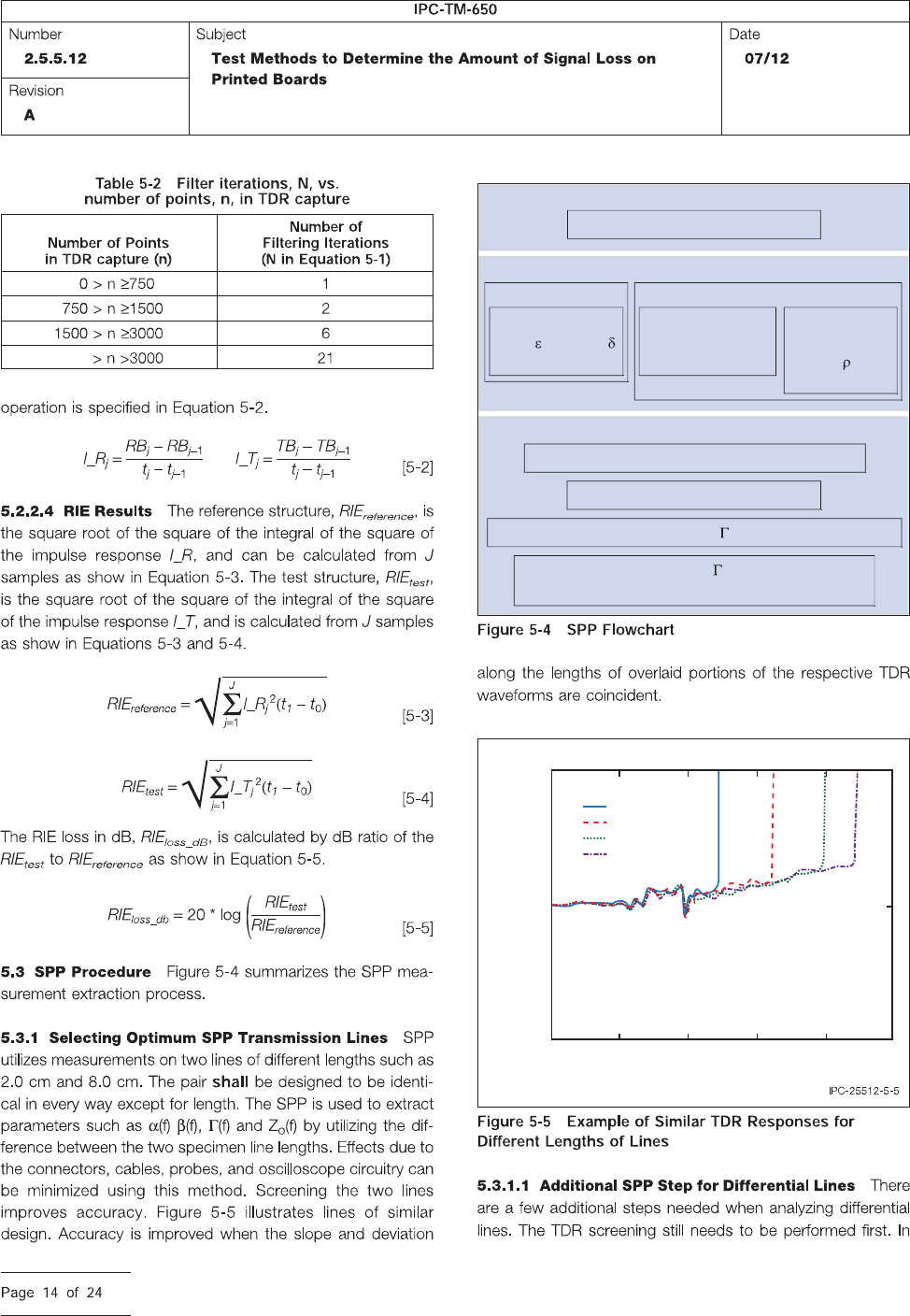
TDR
Select best candidates for line pairs
Low Freq
TDT
disc
Determine
1MHz
r
and Tan
(LCR meter)
Determine
Capacitance/unit
length (LCR meter)
Determine
Resistance/unit
length and
(LCR meter)
Lines
Acquire Impulse response for 2 lines of 2 lengths
Window and filter Impulse response
FFT to get Propagation Constant (Attenuation and Phase)
Use itrative matching of , Att, and low freq
parameters to determine tline modeling parameters
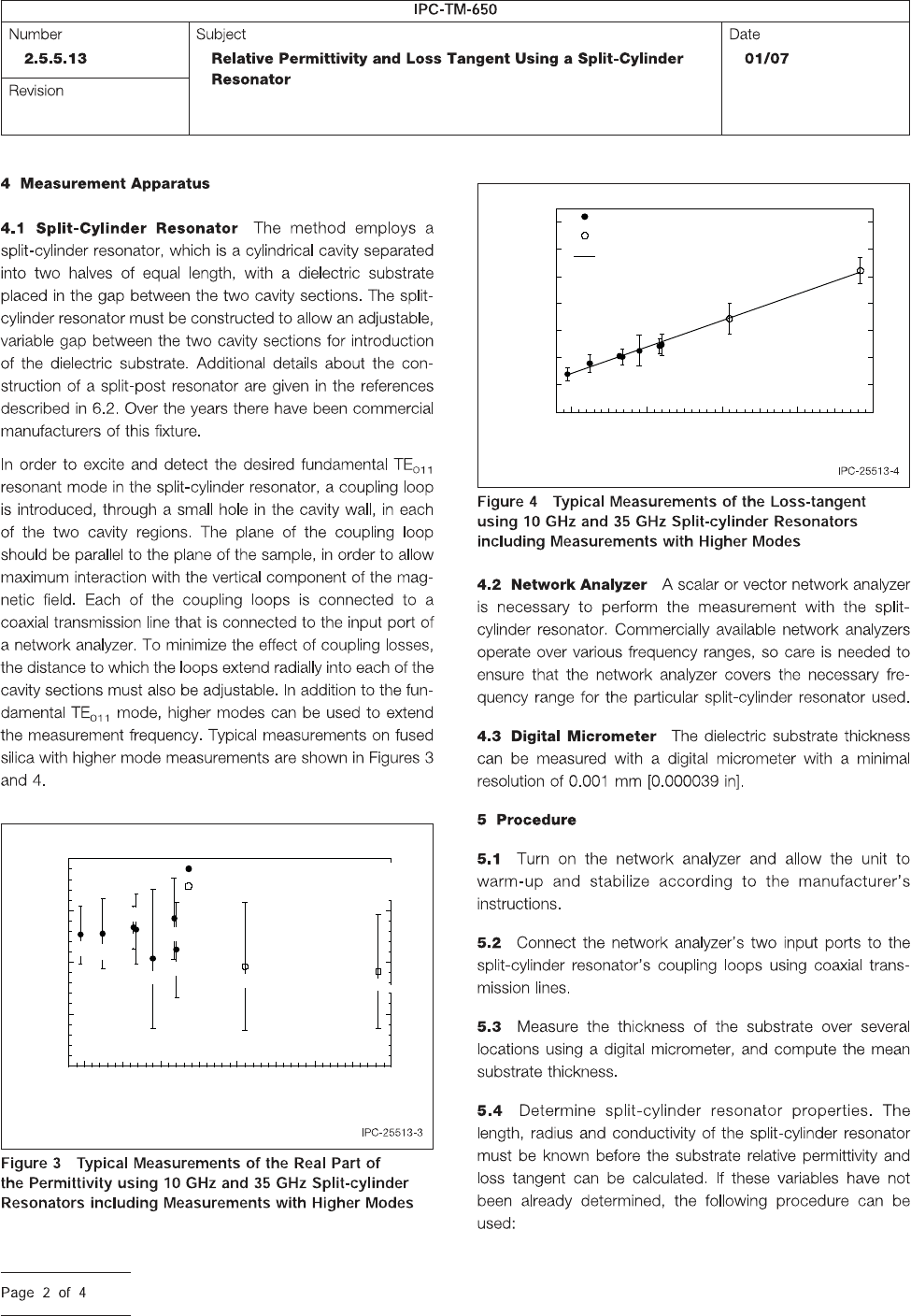
0.3
0.2
0.25
1.5 2.5
Time (nsec)
Voltage (V)
3.52
1=2 cm
1=5 cm
1=8 cm
1=9.8 cm
3 4
3.90
10 20
Frequency (GHz)
30 40 50
3.85
3.80
3.75
3.70
Relative Permittivity
10 GHz Split-Cylinder Resonator
35 GHz Split-Cylinder Resonator
TE
011
TE
013
TE
021
TE
023
TE
017
TE
025
TE
011
TE
013
TE
015
7x10
-4
6
5
4
3
2
1
0
10 20
Frequency (GHz)
30 40 50
Loss Tangent
35 GHz Split-Cylinder Resonator
Linear Least Squares Fit
10 GHz Split-Cylinder Resonator
TE
011
TE
013
TE
021
TE
023
TE
017
TE
025
TE
011
TE
013
TE
015
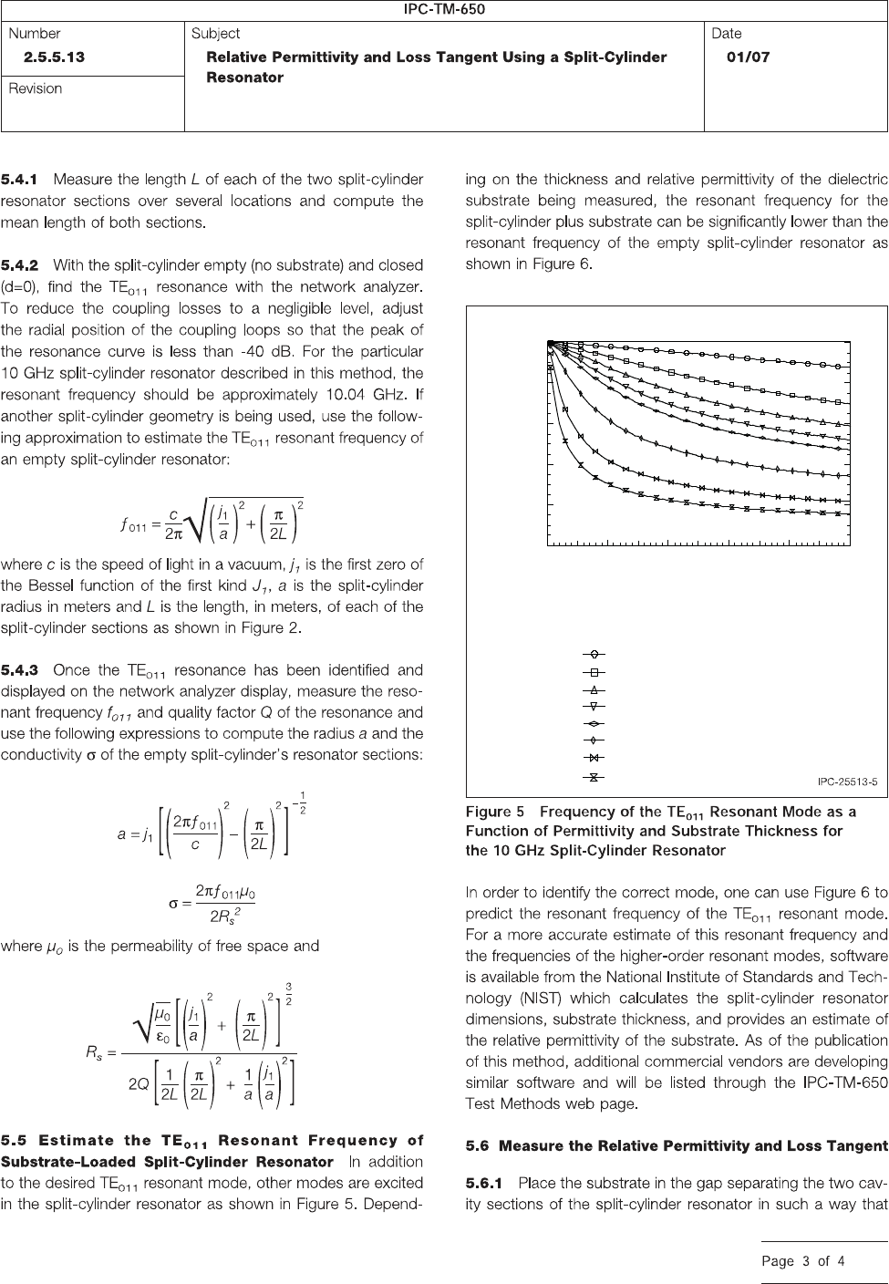
Substrate Thickness (mm)
Sample Relative Permittivity
2
4
6
8
10
20
50
100
10
8
6
4
2
0
0 1 2 3 4
5
TE
011
Resonant Frequency (GHz)