IPC-TM-650 EN 2022 试验方法1.pdf - 第534页
TDR Select best candidates f or line pairs Lo w Freq TDT disc Determine 1MHz r and T an (LCR meter) Determine Capacitance/unit length (LCR meter) Determine Resistance/unit length and (LCR meter) Lines Acquire Impulse res…
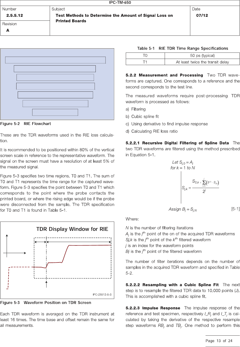
RIE TDR PROCESS
Acquire TDR response for one reference and line under test
Averaging filter of re-sampled TDR waveforms
Cubic spline re-sampling of TDR waveforms
Perform Derivative of filtered TDR waveforms
Determine RIE loss from reference Sample
Determine RIE loss from test Sample
Determine RIE loss ratio
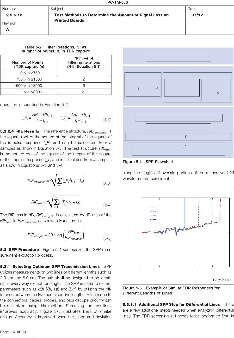
Voltage
Time
Corresponds to probe launch
T0 T1
TDR
Select best candidates for line pairs
Low Freq
TDT
disc
Determine
1MHz
r
and Tan
(LCR meter)
Determine
Capacitance/unit
length (LCR meter)
Determine
Resistance/unit
length and
(LCR meter)
Lines
Acquire Impulse response for 2 lines of 2 lengths
Window and filter Impulse response
FFT to get Propagation Constant (Attenuation and Phase)
Use itrative matching of , Att, and low freq
parameters to determine tline modeling parameters
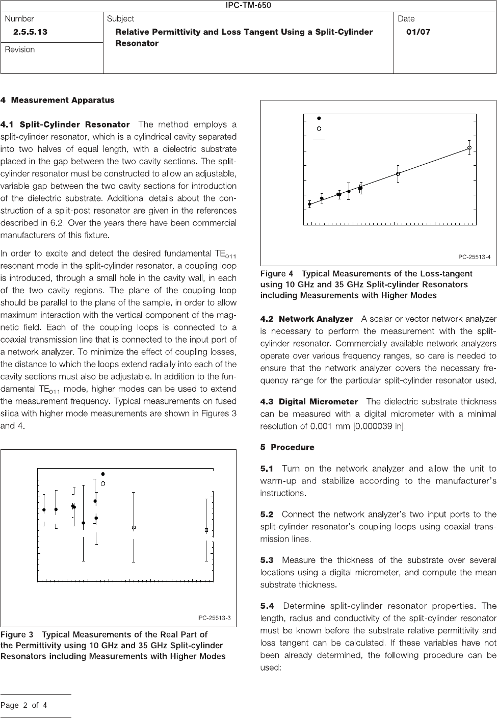
0.3
0.2
0.25
1.5 2.5
Time (nsec)
Voltage (V)
3.52
1=2 cm
1=5 cm
1=8 cm
1=9.8 cm
3 4
3.90
10 20
Frequency (GHz)
30 40 50
3.85
3.80
3.75
3.70
Relative Permittivity
10 GHz Split-Cylinder Resonator
35 GHz Split-Cylinder Resonator
TE
011
TE
013
TE
021
TE
023
TE
017
TE
025
TE
011
TE
013
TE
015
7x10
-4
6
5
4
3
2
1
0
10 20
Frequency (GHz)
30 40 50
Loss Tangent
35 GHz Split-Cylinder Resonator
Linear Least Squares Fit
10 GHz Split-Cylinder Resonator
TE
011
TE
013
TE
021
TE
023
TE
017
TE
025
TE
011
TE
013
TE
015