IPC-TM-650 EN 2022 试验方法1.pdf - 第559页
在线预览 IPC-TM-650 EN 2022 试验方法1.pdf PDF 文档。
Number
Subject
Date Revision
Originating Task Group
MaterialinthisTestMethodsManualwasvoluntarilyestablishedbyTechnicalCommitteesofIPC.Thismaterialisadvisoryonly
anditsuseoradaptationisentirelyvoluntary.IPCdisclaimsallliabilityofanykindastotheuse,application,oradaptationofthis
material.Usersarealsowhollyresponsibleforprotectingthemselvesagainstallclaimsorliabilitiesforpatientinfringement.
EquipmentreferencedisfortheconvenienceoftheuseranddoesnotimplyendorsementbyIPC.
IPC-TM-650
TEST METHODS MANUAL
1 Scope
This test method describes a way to measure the relative permittivity
(
r
) and loss tangent (tan ) (also called dielectric constant,
Dk, and dissipation factor, Df) of base materials for printed boards at frequencies from 1 GHz to 20 GHz using a split post
dielectric resonator (SPDR).
2 Applicable Documents
2.1 IPC-TM-650 Method 2.5.5.2 Dielectric Constant and Dissipation Factor of Printed Wiring Board Material –
Clip Method
2.2 IPC-TM-650 Method 2.5.5.3 Permittivity (Dielectric Constant) and Loss Tangent (Dissipation Factor) of Materials
(Two Fluid Cell Method)
2.3 IPC-TM-650 Method 2.5.5.5 Stripline Test for Permittivity and Loss Tangent (Dielectric Constant and Dissipation Factor)
at X-Band
2.4 IPC-TM-650 Method 2.5.5.5.1 Stripline Test for Complex Relative Permittivity of Circuit Board Materials to 14 GHz
2.5 IPC-TM-650 Method 2.5.5.9 Permittivity and Loss Tangent, Parallel Plate, 1MHz to 1.5 GHz
3 Test Specimens
3.1
All base materials specimens shall have the metallic foil layer removed by etching or other suitable means and shall be
thoroughly cleaned. Each specimen shall be marked in the upper left corner with an engraving pencil or equivalent.
3.2
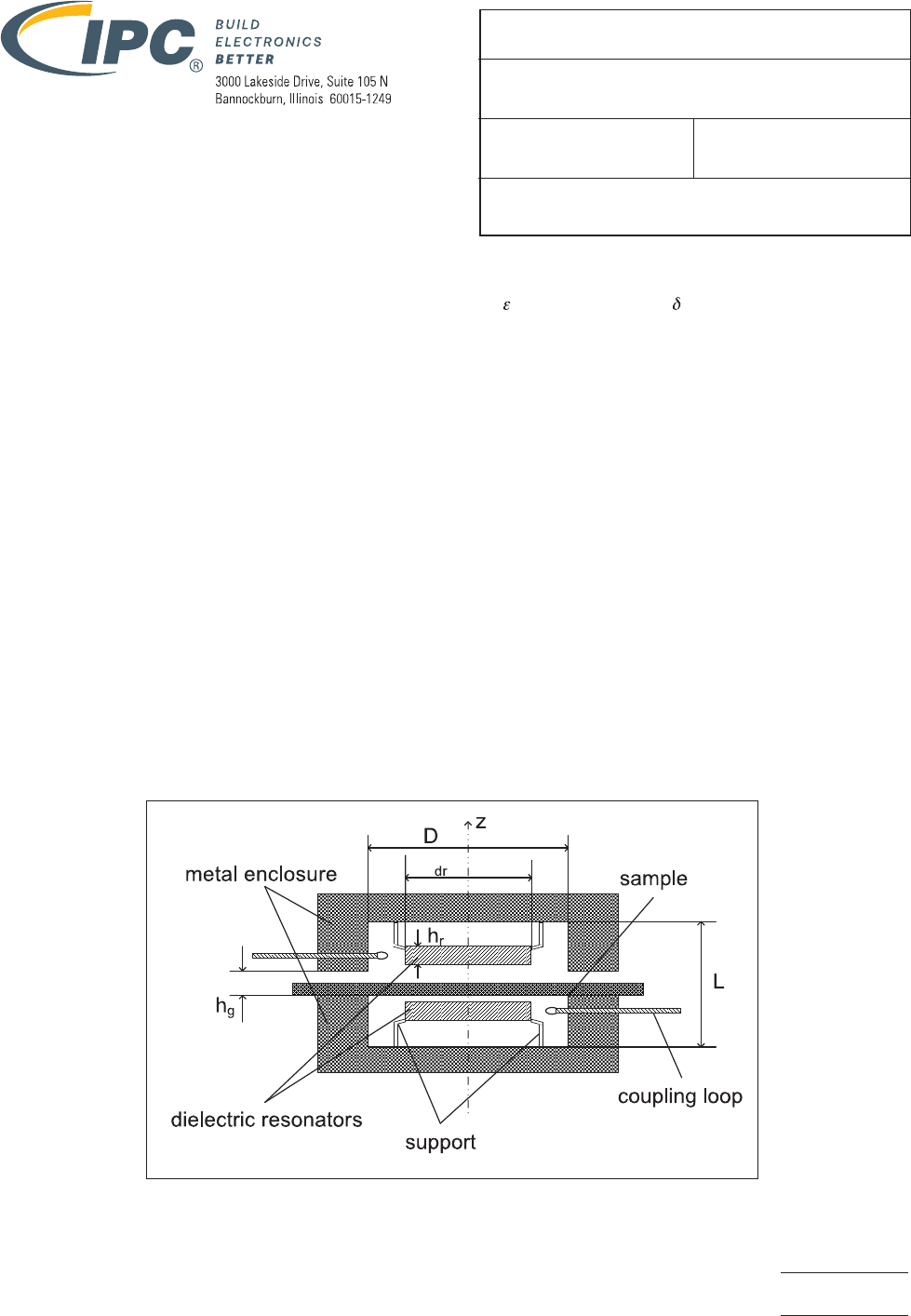
The dimensions of the test specimen shall be larger than the outer dimension of the fixture. See Figure 1.
The size of the specimen shall be larger than the internal diameter D of the metal enclosures, and the maximum thickness of the
specimen shall be smaller than the distance h
g
between the metal enclosures of the fixture.
Figure1–DiagramofSPDRTestFixture
Page 1 of 7
2.5.5.15
06/22 N/A
3-11aIPC-4101TaskGroup
RelativePermittivityandLossTangentUsinga
Split-PostDielectricResonator