IPC-TM-650 EN 2022 试验方法1.pdf - 第501页
S S Z IPC-TM-650 Page 5 of 8
Z
S
S S
S
S
S
Z
Z
S
S S
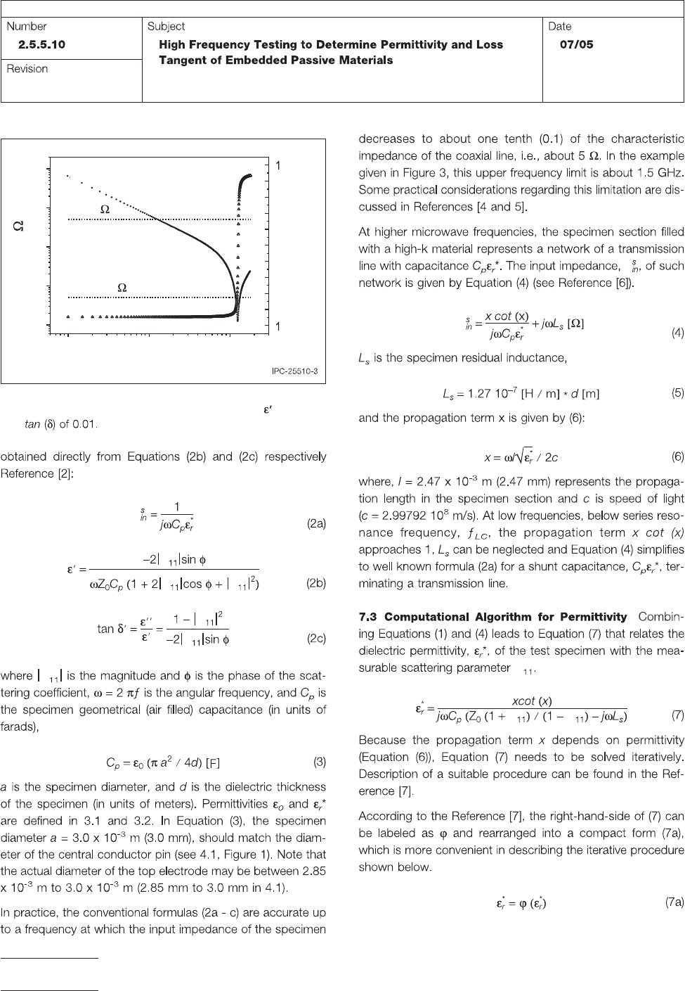
Figure 3 Impedance magnitude (circles) and phase
(triangles) for a 25 µm thick dielectric film with
of 10
and
0.1 1 10
0.01
0.1
1
10
100
- 00
-80
-60
-40
-20
0
20
40
60
80
00
|Z|= 0.05
|Z|= 5
Frequency, GHz
Phase (degree)
|Z|= ( )
IPC-TM-650
Page 4 of 8
S
S
Z
IPC-TM-650
Page 5 of 8
6
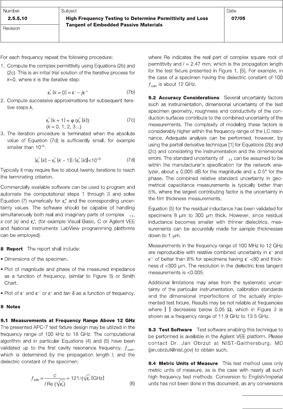
1 Center conductor pin = 3.05 mm
2 Supporting dielectric in the APC-7 section
3 Center conductor in the APC-7 to APC-3.5
4 Supporting dielectric in the APC-3.5 section
5 APC-3.5 section of the adaptor
6 Section A outer conductor (
=7.00 mm)
7 Section B outer conductor ( =7.00 mm)
8 APC-7 mount
8
1
2
Section B
Section A
Section A details
Test Fixture for HF Permittivity of Embedded Passive Materials
Originator: IPC Embedded Passives Test Methods
3
4
5
50
Calibration Plane
METRIC, dimensions are in mm
7
APC-3.5 female mount
IPC-TM-650
Page 6 of 8