IPC-TM-650 EN 2022 试验方法1.pdf - 第584页
Figure 1 Suggested Flex Circuit La yout for In sulation Resistance T est Figure 2 Preattachment of the ACF St rips to the Flex Circuit Page 1 of 2
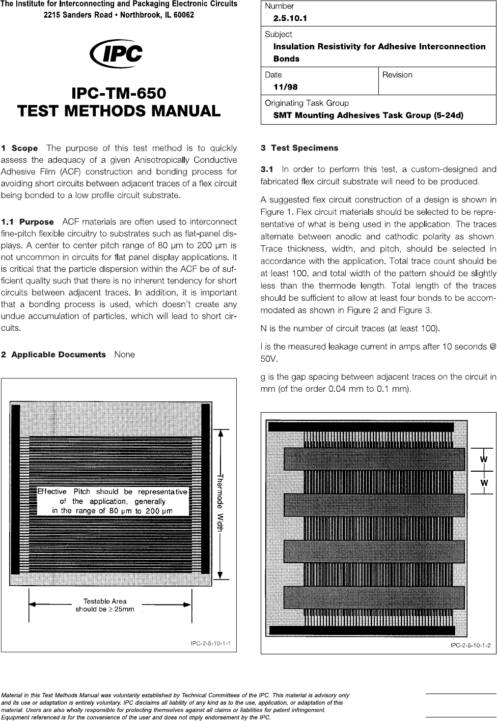
Figure 1 Suggested Flex Circuit Layout for Insulation
Resistance Test
Figure 2 Preattachment of the ACF Strips to the Flex
Circuit
Page 1 of 2
Example
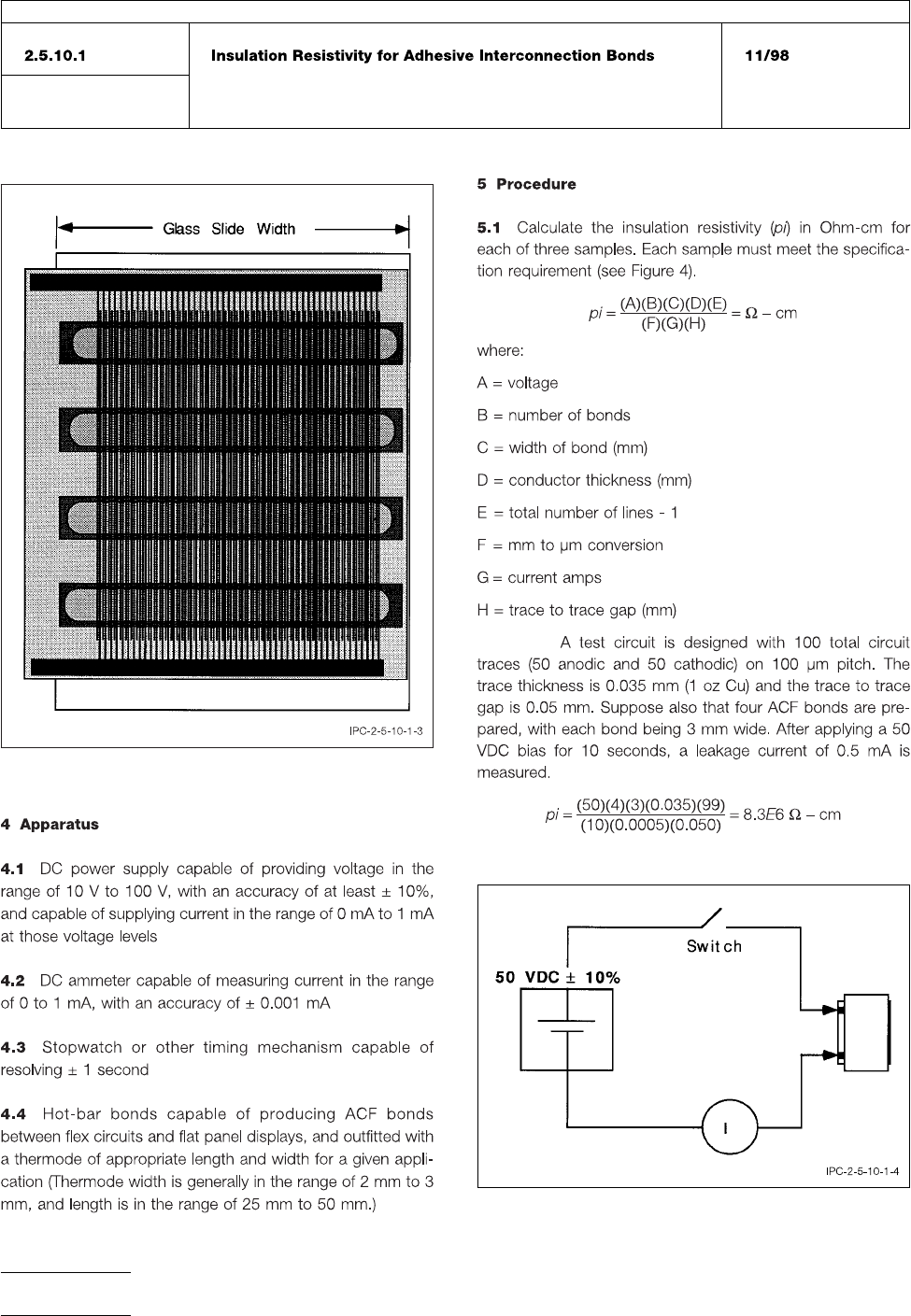
Figure 3 Flex Circuit Containing Four ACF Bond Sites,
After Being Bonded to a Glass Slide
Figure 4 Schematic Diagram for Insulation Resistivity
Measurement
IPC-TM-650
Number
Subject Date
Revision
Page 2 of 2