IPC-TM-650 EN 2022 试验方法1.pdf - 第414页
Page 1 of 1

Number
Subject
Date Revision
Originating Task Group
MaterialinthisTestMethodsManualwasvoluntarilyestablishedbyTechnicalCommitteesofIPC.Thismaterialisadvisoryonly
anditsuseoradaptationisentirelyvoluntary.IPCdisclaimsallliabilityofanykindastotheuse,application,oradaptationofthis
material.Usersarealsowhollyresponsibleforprotectingthemselvesagainstallclaimsorliabilitiesforpatientinfringement.
EquipmentreferencedisfortheconvenienceoftheuseranddoesnotimplyendorsementbyIPC.
IPC-TM-650
TEST METHODS MANUAL
Page 1 of 7
2.4.54
09/2022 N/A
D-33AAIPC-6012AutomotiveAddendumTaskGroup
TestMethodforThermalTransmissionPropertiesof
MetalBasedPrintedBoards(MBPB)
1 Scope
1.1
The scope of the test method is to describe a procedure for measurement of thermal resistance and calculation of an apparent
thermal conductivity for single layer Metal Based Printed Boards (MBPB). This test method has been created to address the
issue of measurement uncertainty for materials with low thermal resistance (high thermal conductivity and/or thin thicknesses).
1.2
Precise measured values of thermal resistance are very important, for multiple applications, especially within automotive
sector, but also in other areas. For materials with a low thermal resistance, the measurement uncertainty increases significantly
when using the steady state measuring method. The target for this test method is to provide good repeatability and reproducibility
in the test result. A certified reference material must be used to guarantee the measurement quality.
The test method shall show a validity of different thermal resistance values represented by different thicknesses and materials
used for the MBPB. The test method shall also describe a reliable thickness measurement.
1.3 Terms and Definitions
Other than those terms listed below, the definitions of terms used in this test method are in accordance
with IPC-T-50.
1.3.1 Thermal Conductivity
Thermalconductivityappliesinthis casetothe bulkvalue of themetallayers (λ
base
orλ
top
see
Table1Equations12and13)orthealuminumbarsforhotorcoldside(λ
h
orλ
c
see Table 1 Equations 1 and 2) and the dielectric
materialfilledwithoxideparticlesofdifferentkindoffillerdegree(λ
die
) (Figure 5).
1.3.2 Apparent Thermal Conductivity
Apparent thermal conductivity includes the bulk thermal conductivity of the dielectric
material filled with oxide particles, the treatment or adhesive layer and the thermal contact resistances (see 1.3.5) to the upper
andlowermetallayers(λ
app.,die
see Table 1 Equation 16).
1.3.3 Total Thermal Resistance
Total thermal resistance R
th,total
applies to the measured thermal resistance of the MBPB and the
contact liquid (R
th,total
see Table 1 Equation 10).
1.3.4 Apparent Thermal Resistance Specimen
Apparent thermal resistance specimen R
th, app,specimen
applies to the measured thermal
resistance of the MBPB. This has an upper and lower metal layer. In-between it has a dielectric layer with the two contact
resistances to the metal layers (R
th, app,specimen
see Table 1 Equation 11).
1.3.5 Thermal Contact Resistance
Thermal contact resistance applies to a contact phenomenon between two bodies. A contact
resistance can arise due to suboptimal surface wetting, high surface roughness or influenced heat flow density at the boundary
layer due to the following parameters: the filler concentration, particle percolation path, particle distribution and particle size.
This contact resistance leads to a variance in measurement results.
1.3.6 Surface Area
Surface area is calculated from the diameter of the meter bars in the dimension mm².
1.4
Technical safety requirements are not defined in this test method. The user must take measures to fulfil all statutory health,
safety and environmental protection requirements.
Page 1 of 1
IPC-TM-650
Number Subject Date
Revision
Page 3 of 7
2.4.54
TestMethodforThermalTransmissionPropertiesof
09/2022
MetalBasedPrintedBoards(MBPB)
N/A
observed temperature range. It is recommended to use high conductive metals for the heat flow meter bars when measuring
high conductive specimens e.g., aluminum alloy with a thermal conductivity of 100 W/(mK) or higher.
4.7
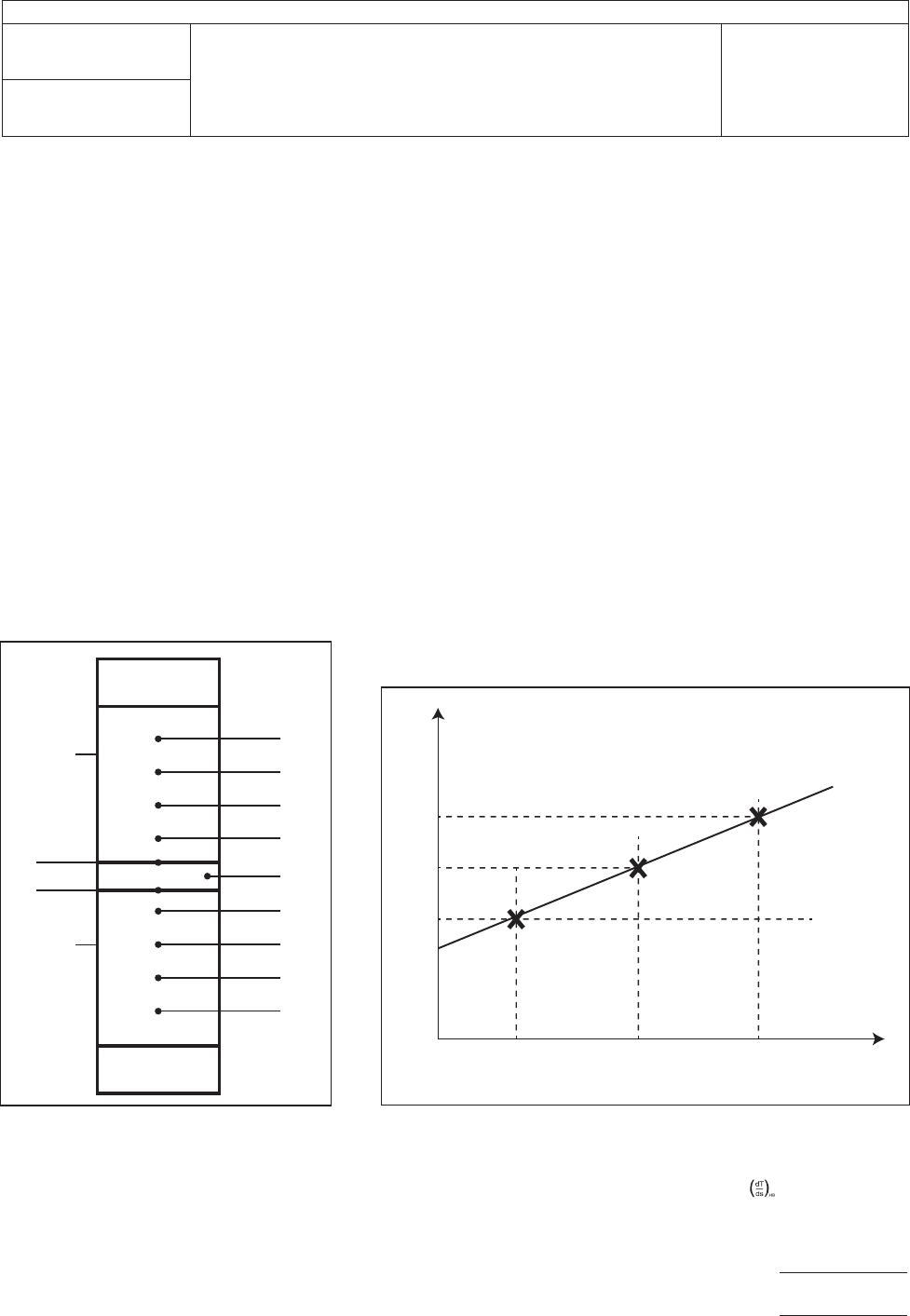
Use more than two thermocouples for the heat flow measurement on each meter bar. It is recommended to use four
thermocouples on every bar. This reduces the error in the slope (Figure 2). The thermocouples should be located in extreme
proximity to the surfaces (about 1.5 mm) (Table 1 Equations 1 to 3). Use thin calibrated thermocouples with a diameter of
< 0.6 mm and a measurement accuracy smaller than +/- 0.1 K. This increases the measurement accuracy significantly.
4.8
The heat flow meter bars are used to determine the temperature of the test surfaces by extrapolating the linear array of meter
bar temperatures to the test surfaces (Table 1 Equations 4, 5 and 6). This should be done for both, the hot side and cold side
meter bars (see Figure 1 Notes 2 and 3).
4.9
The recommended way to create a cooling source in the apparatus is with a metal block cooled by a temperature controlled
circulating liquid (e.g., silicone oil or even water, depending on the temperatures, which should be measured).
4.10
The temperature stability of both, the heating and cooling source, should be very high due to stationary conditions during
the test. Typical stabilities are +/- 0.1 K/(300 seconds).
4.11
The thermal contact resistances between the specimen and the heat flow meter bars is highly dependent on the contact
pressure, which is the reason why this parameter is important. A high contact pressure reduces the thermal contact resistances
and maintains the parallelism and alignment of the surfaces.
4.12
ForMBPBahighpressure≥2.0N/mm²shouldbeappliedduetoasignificantreductionofthethermalcontactresistant.
This guarantees more accurate testing results.
1
2
3
4
8
9
10
11
12
13
14
15
16
7
5
6
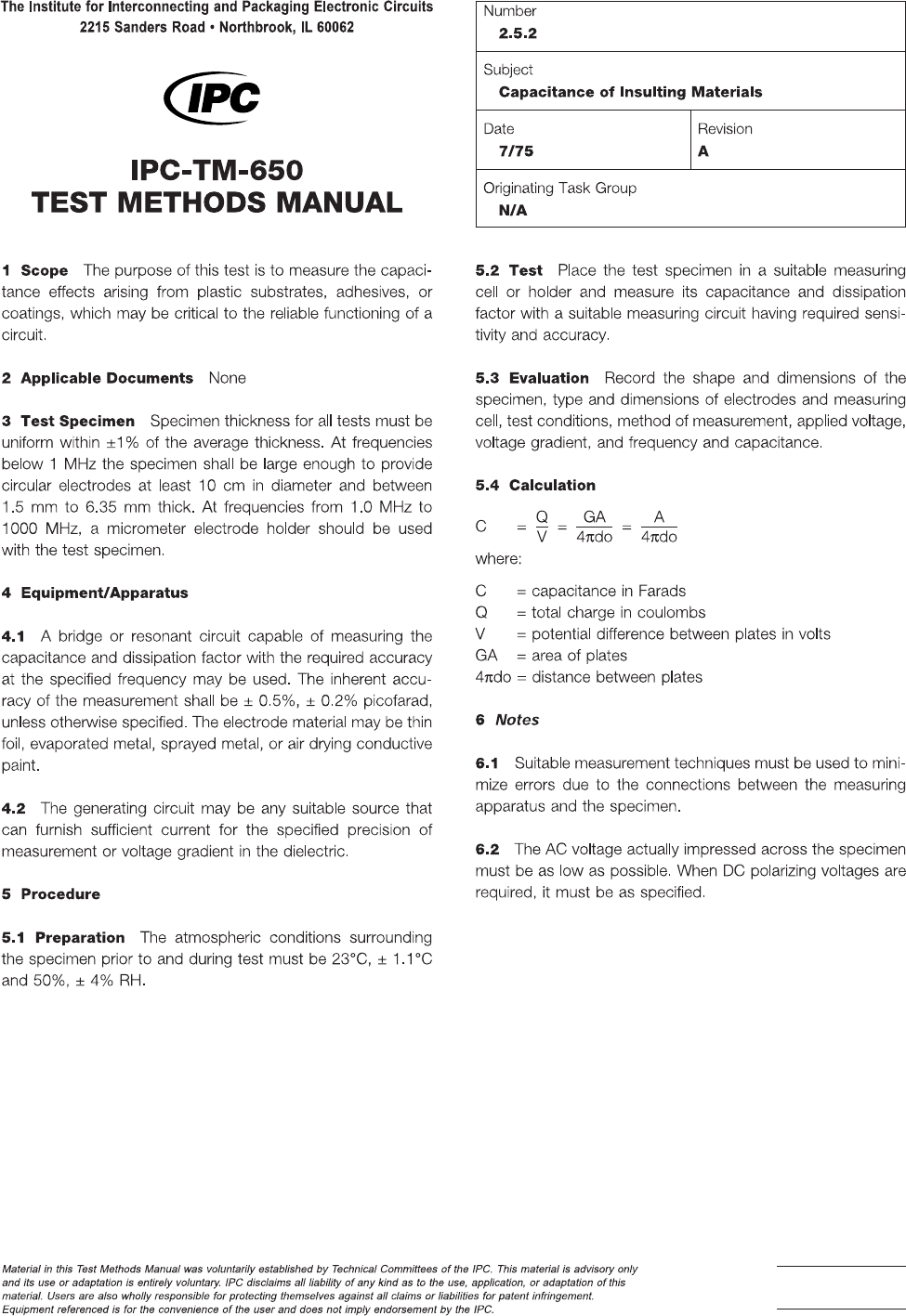
Figure1HotandColdMeterBardswithMore
ThanTwoThermocouples
Note1 – Hot Meter Bar,
see 1.3.1
Note2 – T
H
Note3 – T
C
Note4 – Cold Meter Bar
Note5 – Heat Source
Note6 – Specimen
Note7 – Heat Sink
Note8 – T
HB,1
Note9 – T
HB,2
Note10 – T
HB,3
Note11 – T
HB,4
Note12 – T
S
,
see 6.4.2 and
Table 1
Equation 18
Note13 – T
CB,1
Note14 – T
CB,2
Note15 – T
CB,3
Note16 – T
CB,4
1
2
3
4
5 6
8
7 x
y
Figure2LinearRegressiontoDeterminetheHeatFlowintheHotMeterBar
OutofThreeorMoreThermocouples
Note1 – T
HB,1
Note2 – T
HB,2
Note3 – T
HB,3
Note4 – T
H
Note5 – S
HB,3
Note6 – S
HB,2
Note7 – S
HB,1
Note8 – Slope:
Note9 – x – Path s in m
Note10 – y – Temperature in K