IPC-TM-650 EN 2022 试验方法1.pdf - 第485页
Figure 5-14 Measur ement Zones fo r Diff erential TDR -0.4 -0.3 -0.2 -0.1 0.0 0.1 0.2 0.3 0.4 Time Signal (V) Ch1 Ch2 TDR/Probe Interface Probe/T ransmission Line Interf ace T ransf er Standard Measurement Zone T ransmis…
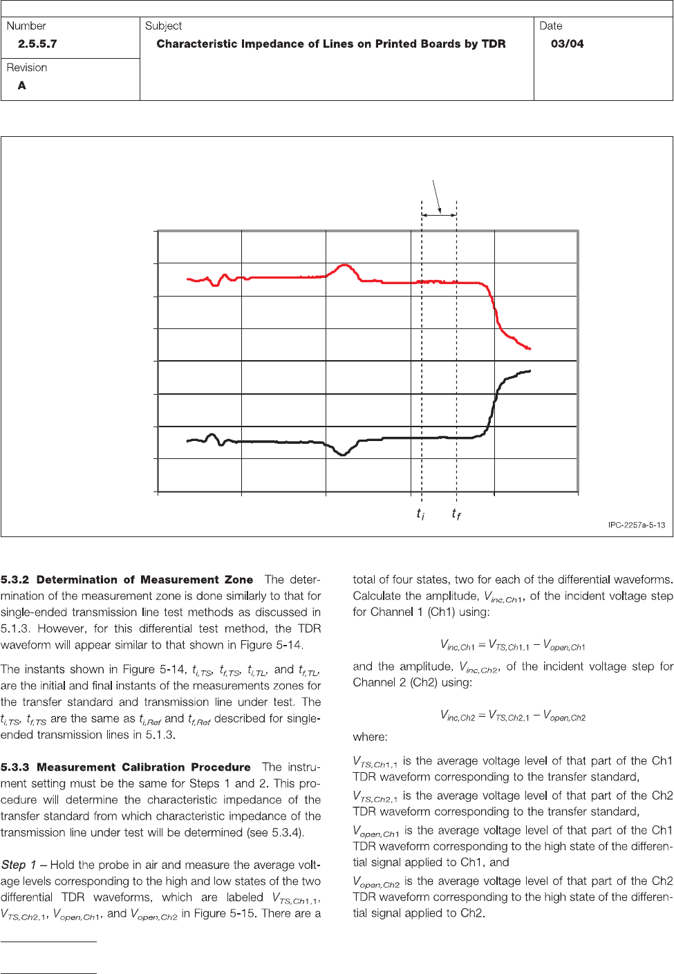
Figure 5-13 Differential TDR Waveform
-0.4
-0.3
-0.2
-0.1
0.0
0.1
0.2
0.3
0.4
Time
Signal (V)
Ch1
Ch2
Transmission Line
Measurement Zone
IPC-TM-650
Page 16 of 23
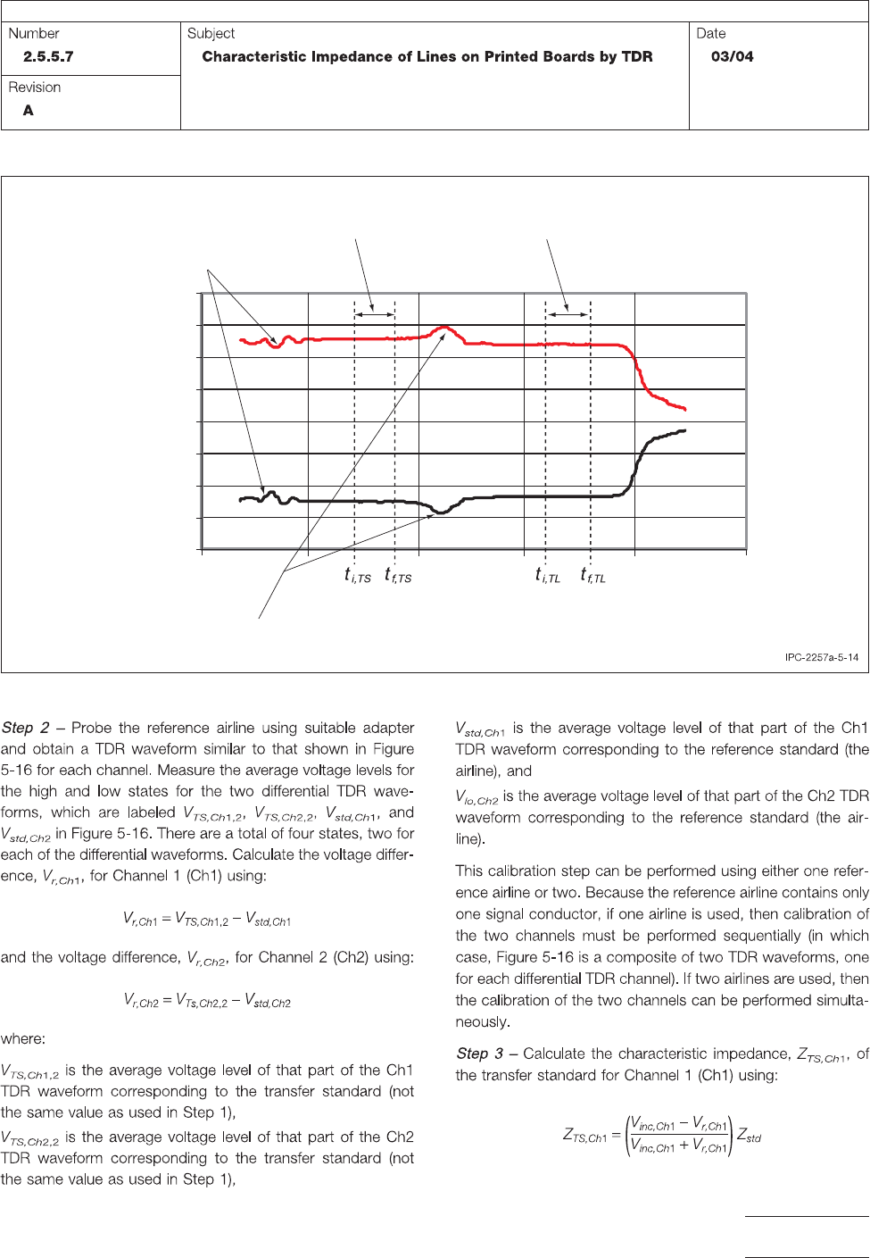
Figure 5-14 Measurement Zones for Differential TDR
-0.4
-0.3
-0.2
-0.1
0.0
0.1
0.2
0.3
0.4
Time
Signal (V)
Ch1
Ch2
TDR/Probe Interface
Probe/Transmission Line Interface
Transfer Standard
Measurement Zone
T
ransmission Line
Measurement Zone
IPC-TM-650
Page 17 of 23
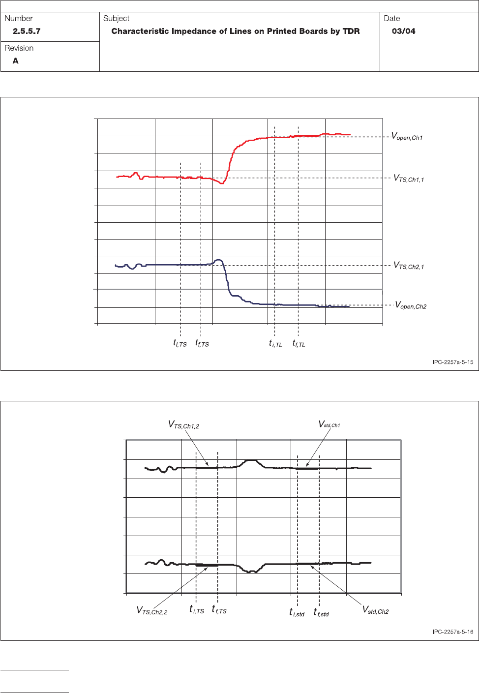
Figure 5-15 Measuring Amplitude for Incident Step
-0.4
-0.3
-0.2
-0.1
0.0
0.1
0.2
0.3
0.4
Signal (V)
Time
Ch1
Ch2
-0.5
-0.6
0.5
0.6
Figure 5-16 Calibration of Transfer Standard
-0.4
-0.3
-0.2
-0.1
0.0
0.1
0.2
0.3
0.4
Signal (V)
Time
Ch1
Ch2
IPC-TM-650
Page 18 of 23