LmrXP142机械手册.pdf - 第100页
Part 5 Chapter 1 Servo System Troubleshooting Edition 3.0 5-1-1 XP-142E Mechanical Reference 1. Servo System T roubleshooting An AC servo system controls all servo axes in the machine. If there is a problem with the serv…

Part 5
Troubleshooting
1. Servo System Troubleshooting . . . . . . . . .5-1-1
This section explains basic procedures for
troubleshooting the machine and its
peripheral devices. Use this section as a
reference for identifying and resolving
minor problems to restore the machine to its
proper condition.
Contact a Fuji agent for serious problems or
repairs that cannot be performed.
Part 5 Chapter 1 Servo System Troubleshooting
Edition 3.0 5-1-1 XP-142E Mechanical Reference
1. Servo System Troubleshooting
An AC servo system controls all servo axes in the machine. If there is a problem with the servo
system, the machine displays an alarm code to notify the operator.
This section describes alarm codes and inspection methods, and should be used as a reference for
troubleshooting and resolving problems.
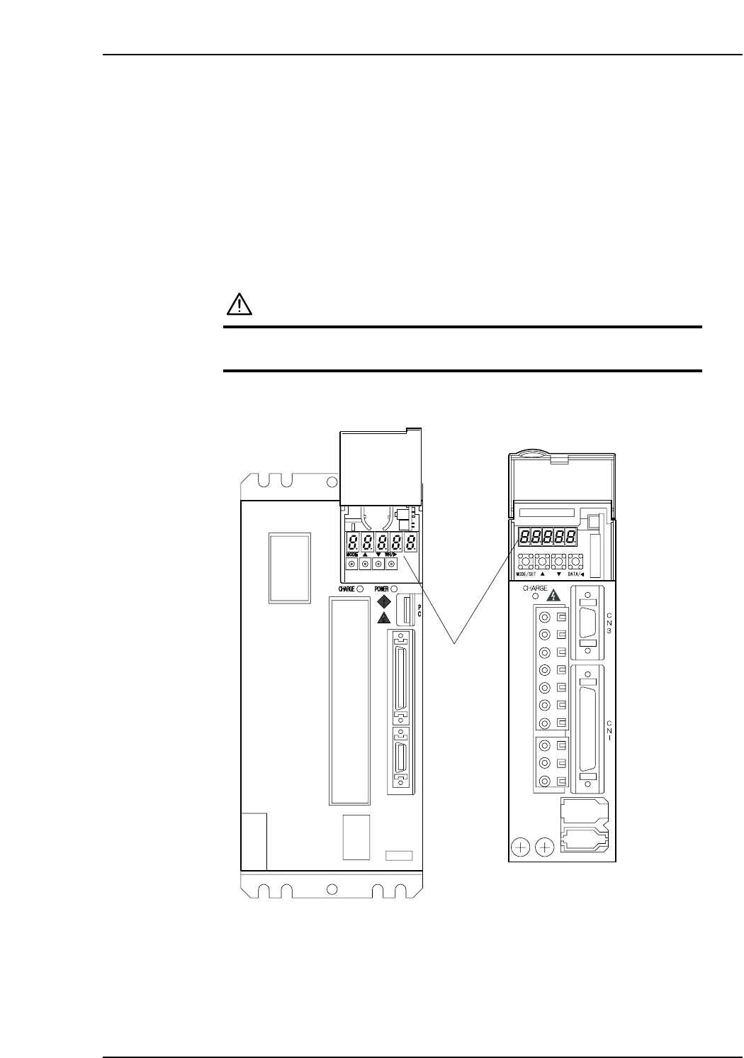
1.1 Alarm Code Display
Each servo amplifier has an LED panel to display alarm codes.
The following illustrations show the location of each servo amplifier’s LED panel.
DANGER
The servo amplifier power terminal is high voltage.
Do not touch the servo amplifier power terminal.
Note: For the Y, G, F, R, Q, and Z-axes, to display the alarm code on the digital operator, connect
the digital operator (JUSP-OP05A) to the servo amplifier CN3 connector.
XP1MA035E
X-axis
Y, G, F, R, Q,
and Z-axes
LED panel
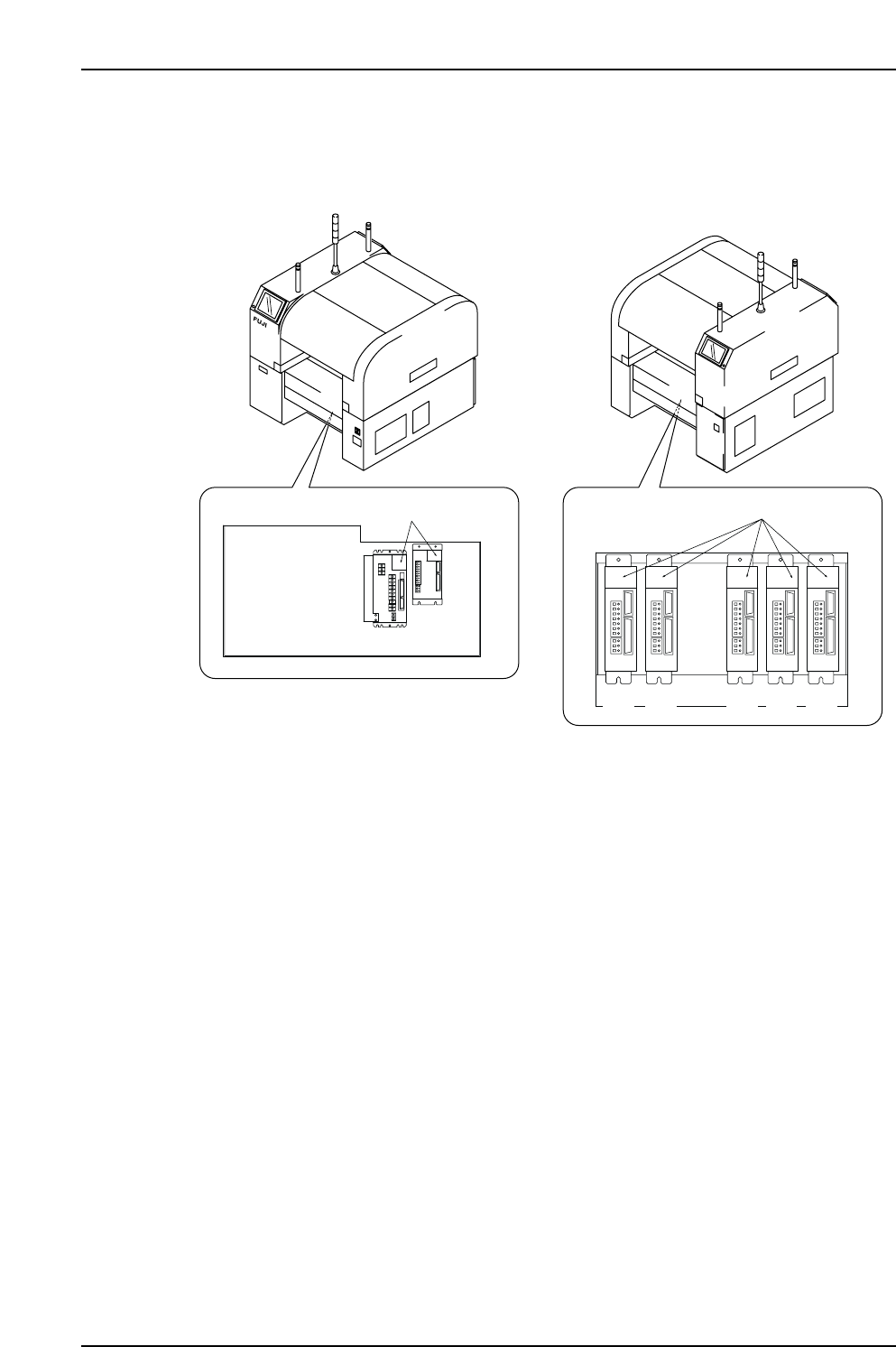
X-, Y-, G-, F-, R-, Q- and Z-Axes Servo Amplifier Alarm Display
Servo box 1
Servo box 2
XP1MR206aE
Front (Side 1)
Rear (Side 2)
LED display
LED display
X-axis
Y-axis
G F R Q Z
Part 5 Chapter 1 Servo System Troubleshooting
Edition 3.0 5-1-2 XP-142E Mechanical Reference